Aa = a b = b b b – Great Planes CAP 232 1.60 ARF - GPMA1410 User Manual
Page 12
❏
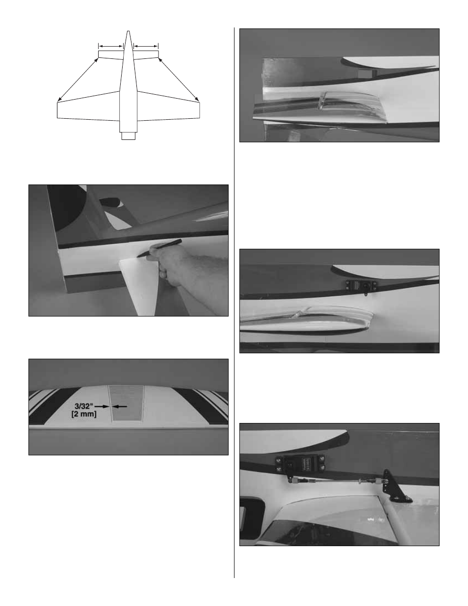
4. Measure the distance from the tip of the stab to the tip
of each wing. Also measure the distance on each side of the
fuselage. Adjust the position of the stab until A=A and B=B.
❏
5. Trace the outline of the fuselage onto the stab using a
felt tip marker or Panel Line Pen. Do this on both the top and
bottom of the stab.
❏
6. Remove the covering from the center section of the
stab 3/32" [2 mm] inside the marked line, being careful not
to cut into the wood structure.
❏
7. Glue the stab in place using 30-minute epoxy. Be sure
to check your measurements periodically to ensure the stab
does not move while the epoxy is curing. Allow the epoxy to
fully harden before proceeding. Once the epoxy has fully
hardened, you may remove the main wing to make the plane
easier to handle.
❏
8. Attach the elevators to the stab following the same
technique used for the ailerons.
❏
9. Locate the two elevator servo bays in the rear of the
fuselage, one on each side of the fuselage. Remove the
covering from these bays using a sharp hobby knife. Note
there are two cutouts on each side that can accommodate a
servo. Cut the covering from the servo bays closest to the
top of the fuselage, nearest the stab.
❏
10. Attach a 24" [610 mm] servo extension to both
elevator servos. Secure the connections with heat shrink
tubing or some other method (not included).
❏
11. Route the servo lead through the fuselage and install
the servo with the output spline toward the nose of the plane
as shown. Center the servo by temporarily connecting it to the
radio system and attach a servo arm. Remove the servo
mounting screws and harden the holes for the servos with thin
CA. Allow the CA to fully dry before reinstalling the screws.
❏
12. Follow the same procedure as the ailerons for
connecting the pushrod and installing the control horns for
both elevator halves.
A
A
A = A
B = B
B
B
12