Great Planes CAP 232 1.60 ARF - GPMA1410 User Manual
Page 13
Note: This section applies to gas engines ONLY.
❏
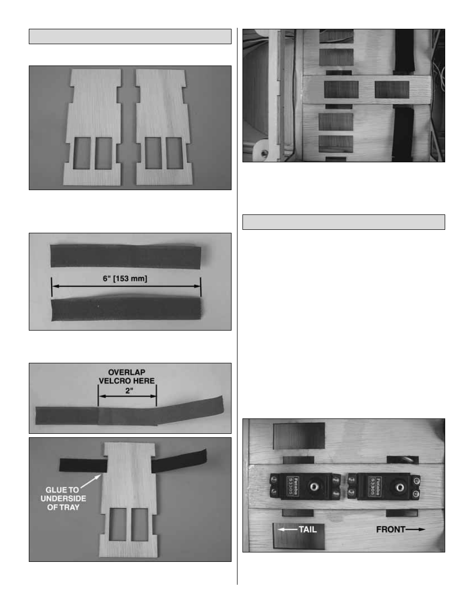
1. Locate the two 1/8" [3.2 mm] plywood radio trays. If you
are installing a gasoline engine, these trays have cutouts for
your throttle servo.
❏
2. Locate the black hook and loop tape supplied with the
ARF. Cut it into equal lengths of approximately 6" [153 mm].
❏
3. Overlap 2" of the hook and loop sides of the tape and
press together. Loop around the plywood radio tray as shown.
❏
4. Align the radio trays as shown in the photo. Glue the
radio trays in place using medium or thick CA. For added
strength, epoxy may be used.
For the CAP 232, there are a couple of variations on how
the rudder servos are installed. They can be mounted in
the tail of the aircraft just aft and below the elevator servos
or they can be mounted in a pull-pull configuration. For
simplicity’s sake in the manual, the setup referenced is the
configuration that required the least amount of additional
weight to balance the model. Of course, it is up to you the
modeler to determine the method used.
The following text details the installation of the pull-pull
system for a typical glow engine installation. If you are
installing a gas engine and do not wish to use the pull-
pull setup, refer to the optional servo location for gas
engine installation section for installing the servos in
the aft servo bays.
❏
1. Attach the rudder using point hinges following the
procedure used for the ailerons and elevators.
❏
2. Install two rudder servos in the servo tray as shown using
the hardware provided by your manufacturer. Be sure each
servo’s output shaft is pointed towards the front of the fuselage.
Install the Rudder
Install the Radio Trays
13