Great Planes CAP 232 1.60 ARF - GPMA1410 User Manual
Page 15
❏
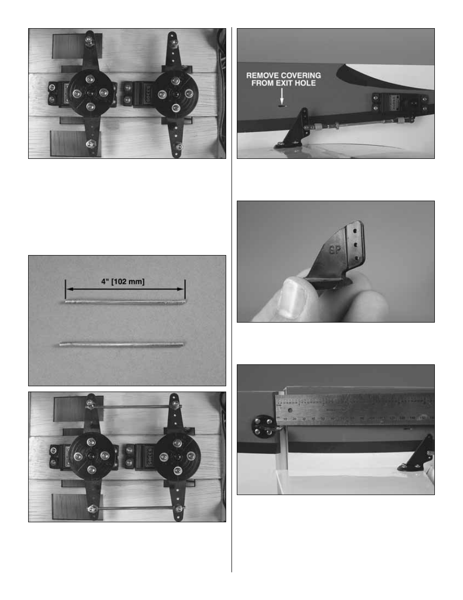
11. Attach both servo arms to the servo, ensuring they
are perfectly parallel.
❏
12. Locate the two 5-1/4" [133 mm] 4-40 pushrod segments.
Cut each pushrod to 4" [102 mm]. Then insert the two pushrods
through the screw lock connectors on both rudder servo arms.
Lock the pushrods in place using 4-40 x 1/8" [3.2 mm] SHCS.
Add a drop of Threadlocker to each screw to hold in place.
❏
13. Remove the covering from the two teardrop shaped
pull-pull cable exits at the rear of the fuselage.
❏
14. Trim the two rudder control horns as shown. This is
necessary to allow the elevator halves to clear the horns.
❏
15. Use a ruler to position the control horns on each side
of the rudder. Align the holes in the control horn with the
hinge line. Drill 1/16" [1.6 mm] pilot holes in the rudder at the
screw mounting locations. Attach the rudder control horns
using four #4 x 1/2" [13 mm] sheet metal screws on each
control horn. Remove the screws and harden the screw holes
with some thin CA. Allow the glue to fully harden before
permanently installing the mounting screws.
15
- Avistar Elite .46 ARF - GPMA1005 (36 pages)
- Avistar Elite .46 RTF - GPMA1605 (20 pages)
- Big Stik 40 ARF MonoKote - GPMA1220 (24 pages)
- Cessna 182 Skylane 40 ARF - GPMA1228 (28 pages)
- Cherokee GP/EP ARF - GPMA1033 (28 pages)
- Christen Eagle 46 ARF - GPMA1431 (36 pages)
- Cirrus SR22 .46-55 ARF - GPMA1363 (32 pages)
- Citabria EP ARF - GPMA1127 (20 pages)
- Curtis P-6E Hawk EP Biplane ARF - GPMA1164 (24 pages)
- Dirty Birdy .60 ARF - GPMA1975 (44 pages)
- Easy Sport 40 ARF MonoKote - GPMA1036 (24 pages)
- Edge 540T EP ARF - GPMA1572 (24 pages)
- ElectroStik EP ARF - GPMA1574 (20 pages)
- ElectroStik EP RxR - GPMA7500 (16 pages)
- Escapade .61 GP/EP ARF - GPMA1201 (28 pages)
- Escapade EP/GP ARF - GPMA1200 (28 pages)
- Escapade MX 30cc ARF - GPMA1210 (32 pages)
- Escapade MX GP/EP ARF - GPMA1202 (24 pages)
- Evader EDF Sport Jet EP ARF - GPMA1800 (24 pages)
- Extra 300SP EP ARF - GPMA1188 (24 pages)
- Extra 300SP Performance Series ARF - GPMA1022 (28 pages)
- Extra 330SC EP ARF - GPMA1129 (20 pages)
- F1 Rocket Evo GP/EP ARF - GPMA1030 (28 pages)
- F-16 Falcon EDF ARF - GPMA1801 (24 pages)
- F-20 Tigershark Electric Ducted Fan ARF - GPMA1875 (16 pages)
- F-86 Sabre Micro EDF TxR - GPMA1771 (12 pages)
- Factor 3D ARF - GPMA1552 (20 pages)
- Fling ARF - GPMA1060 (16 pages)
- Fling DL ARF - GPMA1070 (16 pages)
- FlyLite EP Slow Flyer ARF - GPMA1107 (24 pages)
- Giant Big Stik ARF - GPMA1224 (32 pages)
- Giant Citabria 30cc/EP ARF - GPMA1435 (44 pages)
- Giant Revolver ARF - GPMA1425 (32 pages)
- Giant Super Sportster ARF - GPMA1044 (32 pages)
- Goldberg Super Chipmunk EP ARF - GPMA1928 (20 pages)
- Kunai 1.4M EP ARF - GPMA1815 (16 pages)
- Lanier RC Stinger II - GPMA1010 (24 pages)
- Matt Chapman Eagle 580 46/EP ARF - GPMA1281 (32 pages)
- Mister Mulligan EP ARF - GPMA1485 (32 pages)
- P-51 Mustang GP/EP ARF - GPMA1205 (24 pages)
- P-51 Mustang Sport Fighter .46 EP ARF - GPMA1208 (28 pages)
- PBY Catalina ARF - GPMA1154 (20 pages)
- Phazer EDF ARF - GPMA1802 (24 pages)
- Pluma 3D Bipe ARF ARF - GPMA1130 (24 pages)
- Proud Bird ARF - GPMA1260 (28 pages)