Great Planes 27% Extra 330S ARF - GPMA1413 User Manual
Page 35
35
3D Control Throws
Unless you are an extremely experienced 3D pilot, if
setting up your Extra 330S 1.60 ARF with 3D throws, you
should be able to switch to high or low rate throws during
fl ight in case you fi nd the 3D throws too extreme.
3D
Rates
ELEVATOR:
2" [50mm] up
2" [50mm] down
RUDDER:
6" [150mm] right
6" [150mm] left
AILERONS:
1-1/2" [38mm] up
1-1/2" [38mm] down
IMPORTANT: The Great Planes Extra 330S 1.60 ARF has
been extensively fl own and tested to arrive at the throws
at which it fl ies best. Flying your model at these throws will
provide you with the greatest chance for successful fi rst
fl ights. If, after you have become accustomed to the way
the Extra 330S 1.60 ARF fl ies, you would like to change
the throws to suit your taste, that is fi ne. However, too much
control throw could make the model diffi cult to control, so
remember, “more is not always better.”
Balance the Model (C.G.)
More than any other factor, the C.G. (balance point) can
have the greatest effect on how a model fl ies, and may
determine whether or not your fi rst fl ight will be successful.
If you value this model and wish to enjoy it for many fl ights,
DO NOT OVERLOOK THIS IMPORTANT PROCEDURE.
A model that is not properly balanced will be unstable and
possibly unfl yable.
At this stage the model should be in ready-to-fl y condition
with all of the systems in place including the engine, propeller
and spinner, landing gear, pilot, and the complete radio
system. Electric-powered models should be balanced with
the fl ight batteries installed.
❏
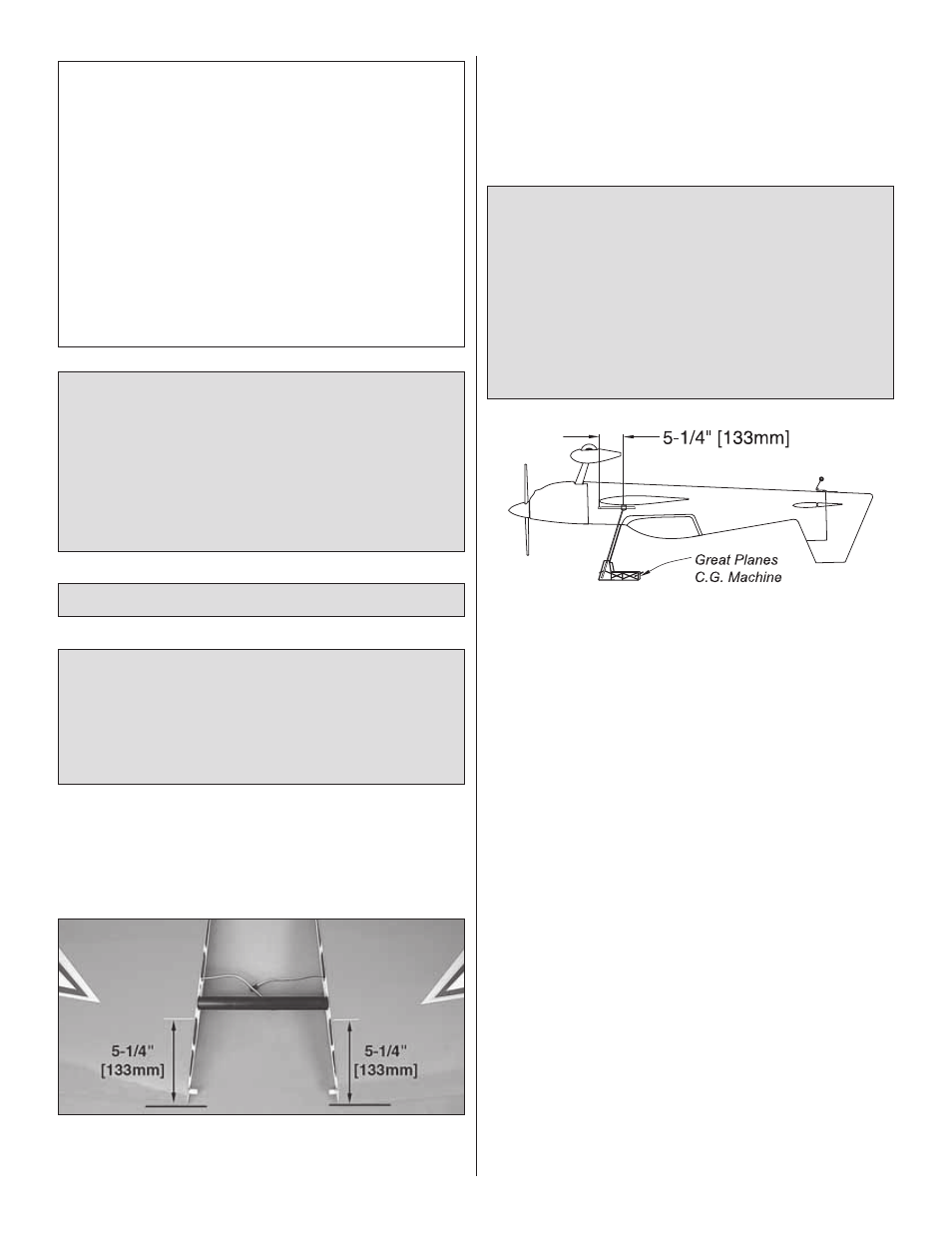
1. If you will be using a Great Planes C.G. Machine, set
the rulers to 5-1/4" [133mm]. If not using a Great Planes C.G.
Machine, slide the wings together with the aluminum joiner. Use
a straightedge and a fi ne-point felt-tip pen to mark the balance
point on the top of both wings 5-1/4" [133mm] back from the
leading edge where they meet the fuselage. Place 1/16" to 1/8"
[1.5 to 3mm] strips of tape over the lines you marked so you will
be able to feel the balance point with your fi ngers when lifting the
model to balance.
This is where your model should balance for the fi rst
fl ights. Later, you may wish to experiment by shifting the
C.G. up to 1/2" [13mm] forward or 1/2" [13mm] back to
change the fl ying characteristics. Moving the C.G. forward
may improve the smoothness and stability, but the model
may then require more speed for takeoff and make it more
diffi cult to slow for landing. Moving the C.G. aft makes
the model more maneuverable, but could also cause it to
become too diffi cult to control. In any case, start at the
recommended balance point and do not at any time
balance the model outside the specifi ed range.
❏
2. Join the wings to the fuselage. With all parts of the
model installed (ready to fl y) and an empty fuel tank (or with
the batteries installed for electric models), place the model
upside-down on a Great Planes C.G. Machine; or, turn it over
and lift it upside-down, placing your fi ngers on the thin strips
of tape at the balance point you marked.
❏
3. If the tail drops, the model is “tail heavy” and the battery
pack and/or receiver must be shifted forward or weight must
be added to the nose to balance. If the nose drops, the model
is “nose heavy” and the battery pack and/or receiver must be
shifted aft or weight must be added to the tail to balance. If
possible, relocate the battery pack and receiver to minimize
or eliminate any additional ballast required. If additional
weight is required, use Great Planes (GPMQ4485) “stick-
on” lead. A good place to add stick-on nose weight is to the
back of the fi rewall inside the fuselage (don’t attach weight
to the cowl–it is not intended to support weight). Begin by
placing incrementally increasing amounts of weight on the
fuselage over the location where it will be permanently
attached inside the model until you can get it to balance.
Once you have determined the amount of weight required, it
can be permanently attached. If required, tail weight may be
added by cutting open the bottom of the fuselage and gluing
it permanently inside.
Note: Do not rely upon the adhesive on the back of the lead
weight to permanently hold it in place. Over time, fuel and
exhaust residue may soften the adhesive and cause the
weight to fall off. Use #2 sheet metal screws, RTV silicone or
epoxy to permanently hold the weight in place.