Great Planes 27% Extra 330S ARF - GPMA1413 User Manual
Page 34
34
Check the Control Directions
❏
1. IMPORTANT: If your Extra 330S 1.60 ARF is powered
by an electric motor, remove the propeller if you haven’t done
so already.
❏
2. If you haven’t done so already, connect all the servos
and the ESC (if using an electric motor), to the receiver.
Route the receiver antenna down through the antenna tube
in the fuselage.
❏
3. Turn on the transmitter and receiver and center the
trims. If necessary, remove the servo arms from the servos
and reposition them so they are centered. Reinstall the
screws that hold on the servo arms.
❏
4. With the transmitter and receiver still on, check all the
control surfaces to see if they are centered. If necessary, adjust
the clevises on the pushrods to center the control surfaces. Be
certain to tighten the 4-40 nuts down to the clevises on
the threaded ends of the pushrods.
❏
5. Make certain that the control surfaces and the carburetor
respond in the correct direction. If any of the controls respond
the wrong way, use the servo reversing in the transmitter
to reverse the servos. Be certain the control surfaces have
remained centered. Adjust if necessary.
Set the Control Throws
Perform the following procedures to measure and set the
control throws according to the measurements in the chart.
The illustrations depict measuring elevator throw, but the
procedure is the same for measuring the ailerons and
rudder. If your radio does not have dual rates, set the throws
to the low-rate settings until you become more familiar with
how the model fl ies. Note: The throws are measured at the
widest part of each control surface.
❏
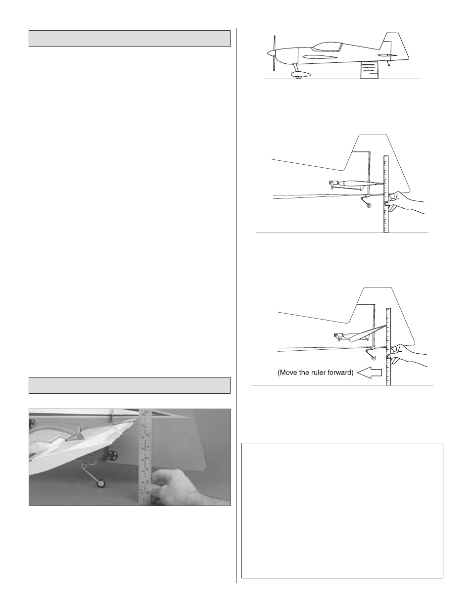
1. Use a small box or something similar to prop up the
fuselage until the wings and horizontal stab are level.
❏
2. With the surface centered, take the initial reading at the
widest part of the surface you are measuring.
❏
3. Defl ect the control surface and move your ruler
forward so it will be contacting the trailing edge. Read the
measurement to get the throw.
These are the recommended high and low rate control
surface throws. If setting up your model with 3D
throws for extreme aerobatics, refer to the 3D chart on
the opposite page:
High Rate
Low Rate
ELEVATOR:
1" [25mm] up
5/8" [16mm] up
1" [25mm] down
5/8" [16mm] down
RUDDER:
4-1/2" [115mm] right 3" [76mm] right
4-1/2" [115mm] left 3" [76mm] left
AILERONS:
1-1/4" [32mm] up
3/4" [19mm] up
1-1/4" [32mm] down 3/4" [19mm] down