Great Planes 27% Extra 330S ARF - GPMA1413 User Manual
Page 16
16
❏
4. Remove the plywood servo arm drilling template.
Keeping the servo wheel in the same orientation as when it
was on the servo, remove the servo wheel from the aft rudder
servo. Mount one of the aluminum pull/pull rudder servo
arms to the wheel as shown with four 2-56 x 3/8" [10mm]
screws and 2-56 nuts–be certain to use threadlocker on
the threads. Optional: After mounting the servo arm, cut off
the screws, then fi le the ends fl at and smooth.
❏
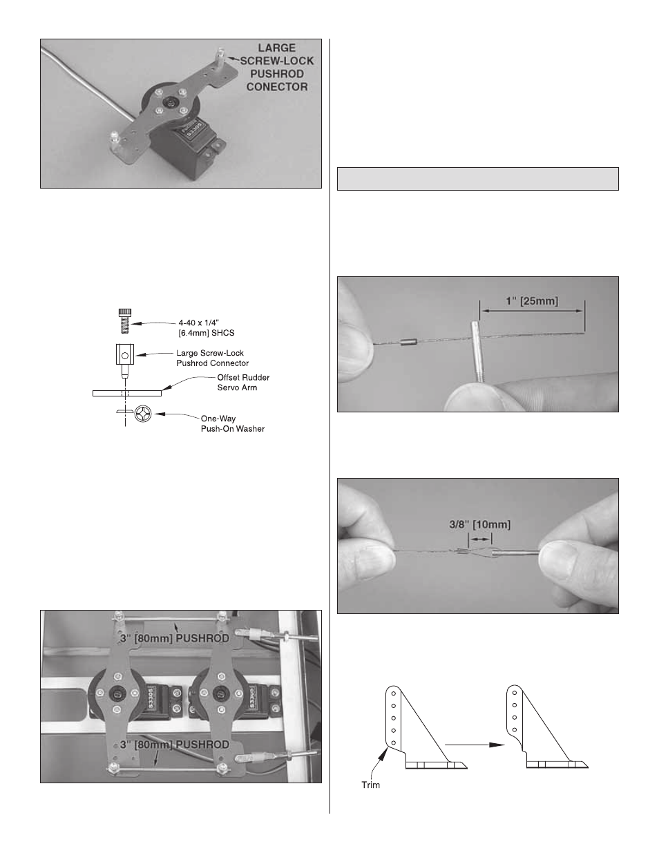
5. Mount two large screw-lock pushrod connectors in the
outer holes on each end of the servo arm and secure the
connectors with a one-way push-on washer. Remount the
servo wheel with the aluminum servo arm to the servo.
Be certain to install the screw that retains the wheel–use
threadlocker if they are machine-thread screws.
❏
6. Mount and setup the other rudder pull/pull servo arm
to the servo wheel on the other rudder servo.
Refer to this photo of the completed rudder servo hookup
while performing the installation in the following steps.
❏
7. Make two 3" [75mm] rudder pushrods from the leftover
4-40 pushrod wire you saved from the elevators. Turn on the
transmitter and receiver. Connect the servo arms on the
rudder servos with the rudder pushrods and four 4-40 x 1/4"
[6.4mm] SHCS. Turn off the radio.
Hook Up the Pull/Pull Rudder Cables
❏
1. Cut the supplied braided steel cable into two equal-
length pieces. (There should be enough cable to make two
sets–in case you make a mistake.) Set one of the pieces
aside in case you need it as a spare.
❏ ❏
2. Cut the other piece of cable in half again. Slide a
copper swage and a threaded brass coupler onto one end of
one of the cables. There should be approximately 1" [25mm]
of cable coming from the coupler.
❏ ❏
3. Loop the cable over and slip it into the swage. Adjust
the position of the swage so the cable makes a loop and there
is approximately 3/8" [10mm] between the end of the swage
and the coupler. Squeeze the swage tightly with pliers.
❏ ❏
4. Trim the bottom hole from two control horns as shown.