Great Planes 27% Extra 330S ARF - GPMA1413 User Manual
Page 15
15
pushrods. Hold the horns to the rudder and drill 3/32" [2.4mm]
holes 1/2" [13mm] deep for the mounting screws – same as
the aileron horns, the rudder horns should be mounted all the
way forward. Mount the horns to the rudder with #4 x 1/2"
[13mm] screws. Don’t forget to remove the screws. Harden the
holes with a few drops of thin CA, allow to harden, and then
remount the horns.
Hook Up the Elevators
Note that, because the elevator servos move in opposition,
they must be connected to two different channels and linked
electronically via mixing in the transmitter (or connected to
a Futaba Servo SR-10 Dual Servo Reverser (FUTM4150)
so that one of the servos can be reversed).
Refer to the previous photo showing the servos while
hooking up the elevators.
❏
1. If mounting the receiver to the forward servo tray,
connect 36" [910mm] servo extension wires to the elevator
servos. If mounting the receiver to the aft servo tray, connect
24" [610mm] servo extension wires to the elevator servos. If
not yet certain where you will be mounting the receiver, you
may connect the extensions later.
❏
2. The same as was done for the servo extension wires on
the aileron servos, secure the connections with 3" [75mm]
pieces of heat-shrink tubing cut in half.
❏
3. Guide the elevator servo wires down through the
fuselage and mount the servos. Note that the servo output
shafts are forward.
❏
4. Select the plastic servo arm adapters for your servos
– “F” is for Futaba, “H” is for Hitec and “A” is for Airtronics
and JR.
❏
5. Same as the aileron servos, use the 3mm screws
supplied with your radio system to mount the servo wheels/
arms. Drill out the hole in the metal servo arms and plastic
adapters included with this kit with a #32 (.116" [3mm]) drill.
❏
6. Temporarily mount the servo arms to the servos using
the appropriate servo adapters and servo screws.
❏
7. Make two 5-1/2" [140mm] elevator pushrods from two
4-40 x 12" [300mm] pushrods. If mounting the rudder servos
inside the fuselage with the pull/pull setup, save the leftover
pieces of pushrod you cut off for connecting the rudder
servos later. Use the same techniques described for making
the aileron pushrods to solder large metal solder clevises to
the ends of the elevator pushrods.
❏
8. Connect the pushrods to the servo arms. Then, connect
the horns to the other end of the pushrods. Hold the horns
to the elevators and drill 3/32" [2.4mm] holes 1/2" [13mm]
deep for the mounting screws – same as the aileron and
rudder horns, the elevator horns should be mounted all the
way forward. Mount the horns to the elevators with #4 x 1/2"
[13mm] screws. Don’t forget to remove the screws, harden
the holes with a few drops of thin CA and allow to harden
before remounting the horns.
If you already mounted the rudder servos in the back of the
fuselage, skip ahead to page 18 and mount the tail gear.
Mount the Pull/Pull Rudder Servos
❏
1. Mount the rudder servos in the rudder servo tray in
the fuselage by drilling 1/16" [1.6mm] holes for the screws,
temporarily installing, removing, and hardening the holes with
thin CA. Connect both servos to a dual servo connector. Then
temporarily connect the connector into the rudder channel in your
receiver. Also connect a receiver battery and an on/off switch to
the receiver so you can operate the servos with the transmitter.
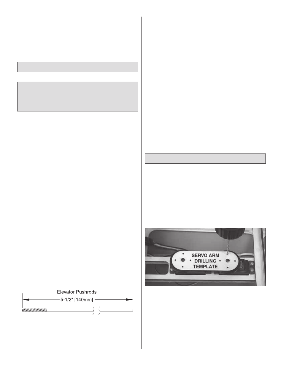
Refer to this photo for the following two steps.
❏
2. Turn on the transmitter and receiver and center the
rudder trim on the transmitter. With the rudder servos
powered up and the trims centered, mount a servo wheel
to each servo. Use the servo arm screws that came with the
servos to mount the plywood servo arm drilling template to
the servos over the wheels.
❏
3. With your radio system still on, use the holes in the
plywood servo arm drilling template as a guide to drill 3/32"
[2.4mm] holes through the servo wheels. Now you may turn
off the radio.