Great Planes 27% Extra 330S ARF - GPMA1413 User Manual
Page 12
12
❏
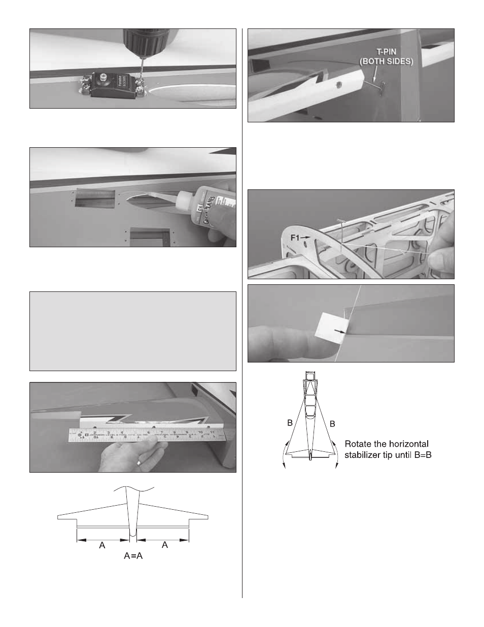
2. Place each servo in its opening and drill 1/16" [1.6mm]
holes for the mounting screws.
❏
3. Temporarily mount each servo with the screws supplied
with your radio system. Remove the screws and add a few
drops of thin CA to each hole.
Note: The following stab alignment procedure may appear
to be extensive, but these are the steps necessary to build
a model with a properly-aligned horizontal stabilizer that will
fl y correctly. You could skip all the alignment steps and just
eyeball it, but you may end up with a crooked model that
won’t fl y straight. Please follow all of the instructions and
take your time to end up with an airplane that is straight
and true.
❏
4. Slide the stab into the fuselage. Center the trailing edge
(TE) in the fuselage by taking accurate measurements on
both sides.
❏
5. Once you have the trailing edge centered, stick large
T-pins through the trailing edge tightly against both sides of
the fuselage. This will keep the trailing edge centered while
rotating the leading edge in the next step.
❏
6. Push another T-pin through the top of F1 at the
centerline. Tie a small loop in one end of an approximately
60" [1.5m] piece of non-elastic string (such as K+S or Kevlar
fi shing string). Fold a piece of masking tape over the string
near the other end and mark an arrow on it. Swing the string
over to the tip on one side of the stab and slide the tape
along the string until the arrow aligns with the tip. Swing the
string over to the same spot on the other side of the stab and
rotate the stab. Move the tape until both sides are the same
and the stab is squared.
One more alignment procedure to go…