Install the hardware – Great Planes Extra 300S 40 Kit - GPMA0235 User Manual
Page 40
❏
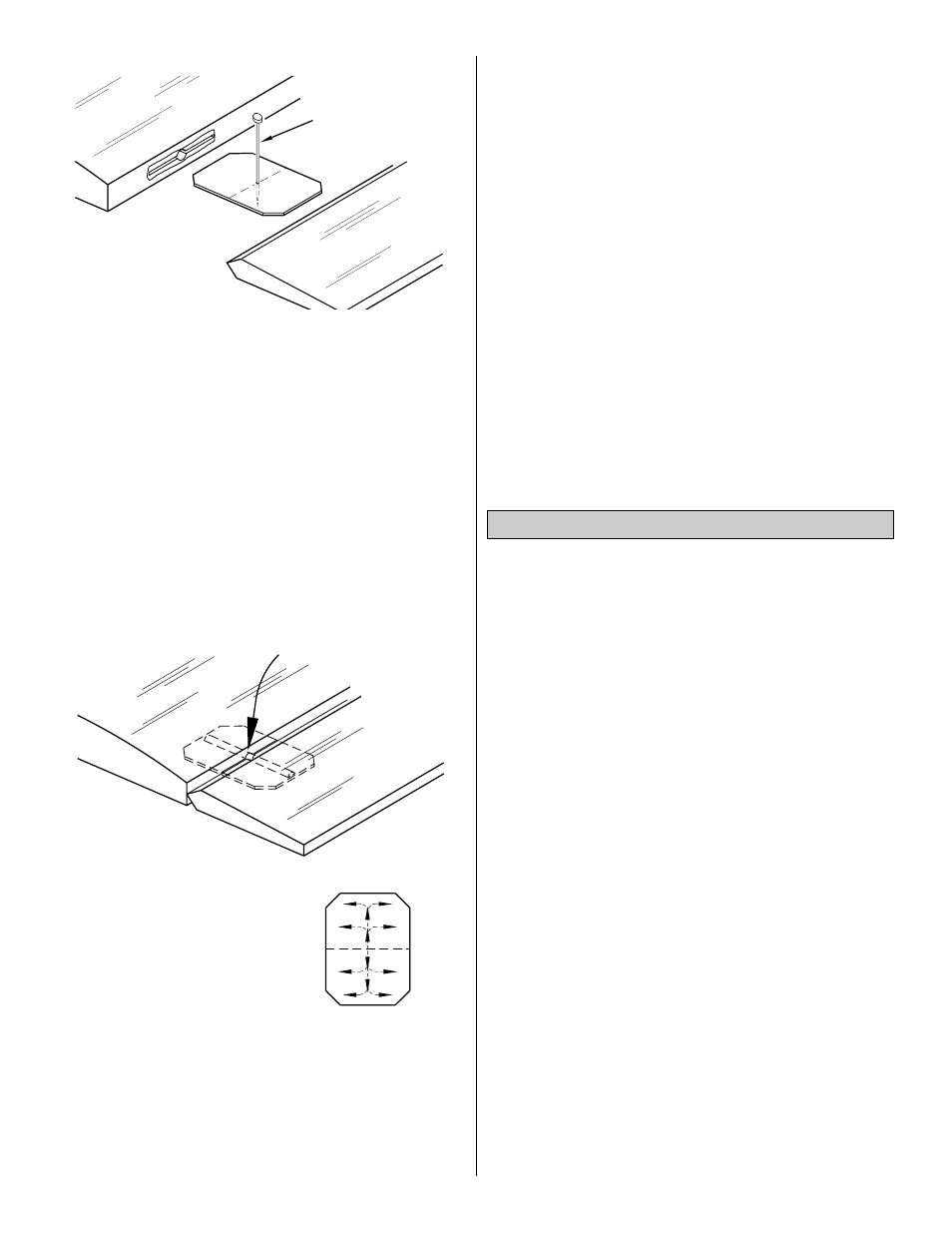
5. Without using any glue, fit the hinges in the elevators
or stab, then fill the holes in the elevators for the joiner wire
with 30-minute epoxy. Join the elevators to the stab and
joiner but do not glue the hinges yet. As you join the
elevators to the stab, confirm that the hinges are equally
inserted in the elevators and the stab. You may insert a
small pin in the center of the hinges to keep them centered.
❏
6. Remove excess epoxy that squeezes out of the
elevators with a cloth dampened with alcohol. Close the
hinge gap to 1/32" or less–it is best to have a
slight gap to
avoid inadvertently gluing the control surfaces together.
Remove the pins if you have used them to center the hinges.
❏
7. Add 6 drops of thin CA to the center of all the hinges
on both the top and the bottom.
Do not use accelerator on any of the hinges. Do not glue
the hinges with anything but thin CA and do not attempt
to glue one half of the hinge at a time with medium or
thick CA. They will not be properly secured and the
controls could separate while the model is in flight.
❏
8. Join the rudder to the fin with the hinges and use
30-minute epoxy to simultaneously glue the tail gear wire in
the rudder and the tail gear bearing in the fuse. Do not
glue the nylon bearing to the rudder. Glue the hinges in
position with thin CA.
Hint: Apply a little petroleum jelly to the tail gear wire where
it passes through the nylon bearing. This will prevent the
wire from being glued into the bearing.
❏
9. Prepare the hinge slots in the ailerons the same way
you did for the tail surfaces.
❏
10. Use a toothpick to pack the torque rod holes in the
ailerons with 30-minute epoxy, then join the ailerons to the
wing with the hinges. Glue the hinges with thin CA. Wipe
away the epoxy that is squeezed out of the ailerons with a
paper towel and alcohol.
❏
11. If you have not yet installed and connected the
control horns and elevator, rudder and aileron pushrods
return to step 6 on page 32 for instructions on how to do so.
❏
1. Assemble the fuel tank per the manufacturers
instructions. Connect approximately 1' of fuel tubing to the
fuel pick-up fitting on the tank and 1' of fuel tubing to the
pressure fitting on the tank. Slide the tank through the
opening in F-2B as you route the lines through the holes
you drilled in the firewall (you may have to remove the
servos to install the fuel tank). Secure the tank to the tank
floor by hooking #64 rubber bands to the wood rails you
glued to the bottom of the tank floor.
❏
2. Install a 1" tail wheel with a 3/32" wheel collar.
❏
3. Install the wheels in the wheel pants (don't forget the
masking tape so the screw doesn't scratch the paint), then
mount the wheel pants to the landing gear. Secure the 8-32
nuts with a drop of thread lock.
❏
4. Mount the landing gear to the fuselage with the 8-32 x
3/4" SHCS and #8 washers.
❏
5. Install the elevator, rudder and throttle pushrods, then
install the control horns and hook them up the same way
you did earlier.
❏
6. Wrap the receiver and battery pack in at least 1/4" of
foam rubber, then fit them ahead of former F-2B in the
location shown on the plan. Pack extra foam in the
compartment to keep the receiver and battery pack from
dislodging during aerobatics or a rough landing.
❏
7. Mount the receiver switch in a convenient location that
will not interfere with the servos and pushrods inside
the fuselage.
Install the Hardware
THE CA WICKS
ALONG THE "TUNNELS"
TO THE ENTIRE
HINGE SURFACE
ASSEMBLE, THEN APPLY 6 DROPS
OF THIN CA TO CENTER
OF HINGE, ON BOTH SIDES
TEMPORARY PIN
TO KEEP HINGE
CENTERED
40