Great Planes Extra 300S 40 Kit - GPMA0235 User Manual
Page 32
❏
2. Cut one of the outer pushrod guide tubes left over
from the rudder and elevator guide tubes to a length of
7-3/4". Use coarse sandpaper to roughen the outside of the
tube so the glue will stick.
❏
3. Fit the tube through the hole you drilled in the firewall
and former F-2B.
Note: If you are mounting a 4-stroke engine you may have
to drill another hole in F-2B to reroute the pushrod.
❏
4. Bend and cut the 17-1/2" throttle pushrod wire to fit
your engine installation using the drawing on the fuselage
plan as a guide. Install a nylon clevis and insert the pushrod
through the guide tube. Make adjustments to the bends in
the wire so the pushrod aligns with the carburetor arm on
the engine, then temporarily connect the clevis to the carb
arm. Temporarily mount the muffler and make sure the
throttle pushrod will not interfere with the muffler. Make
adjustments to the bends in the wire if necessary.
❏
5. Install the servos in the servo tray spacing them apart
as necessary so the servo arms do not interfere with each
other. Temporarily install the brass Screw-Lock
™
Pushrod
connector in the throttle servo arm, then adjust the bend in
the throttle pushrod if necessary and fit it into the connector.
Note: Some modelers prefer to install the pushrods and
control horns after the model is covered. If this is your
preference skip ahead to step 15. Return to step 6 after you
have covered the model and joined the control surfaces to
the model with the hinges.
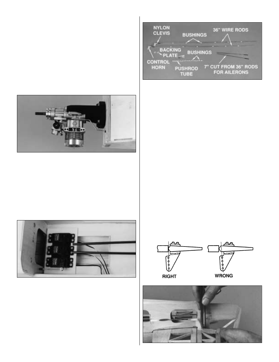
Use this photo for the next three steps.
❏
6. Cut 7" off one end of both 36" wire rods. Set the short
pieces aside and save them for the aileron pushrods.
Thread a nylon clevis about 20 turns onto the end of one of
the long rods, then remove the backing plate from a nylon
control horn and connect the horn to the clevis in the outer
hole. Make another pushrod assembly from the other long
rod with a clevis and control horn.
❏
7. Cut twelve 3/8" bushings from the 6-1/2" plastic inner
pushrod tube. Slide six bushings, evenly spaced, onto each
pushrod. Adjust the bushings nearest the ends of the rods
so they will not interfere with the ends of the guide tubes
and possibly become jammed during flight. If the bushings
slide onto the wires without much resistance use a drop of
thin CA to hold them in position.
Hint: Before installing the bushings, use a cloth saturated
with denatured alcohol or other solvent to wipe off the oil
left on the wires from the manufacturing process.
❏
8. Trim the plastic pushrod guide tubes that are glued
into the fuselage so they “end” about 2" aft of the elevator
and rudder servo arms. If you've used CA to secure the
plastic bushings on the wire pushrods, make sure it has
fully cured, then slide the pushrods into the guide tubes
from the back of the fuselage.
32