Balance the model (c.g.) – Great Planes Yak-55M 50-55cc Sport / 3D ARF - GPMA1230 User Manual
Page 28
28
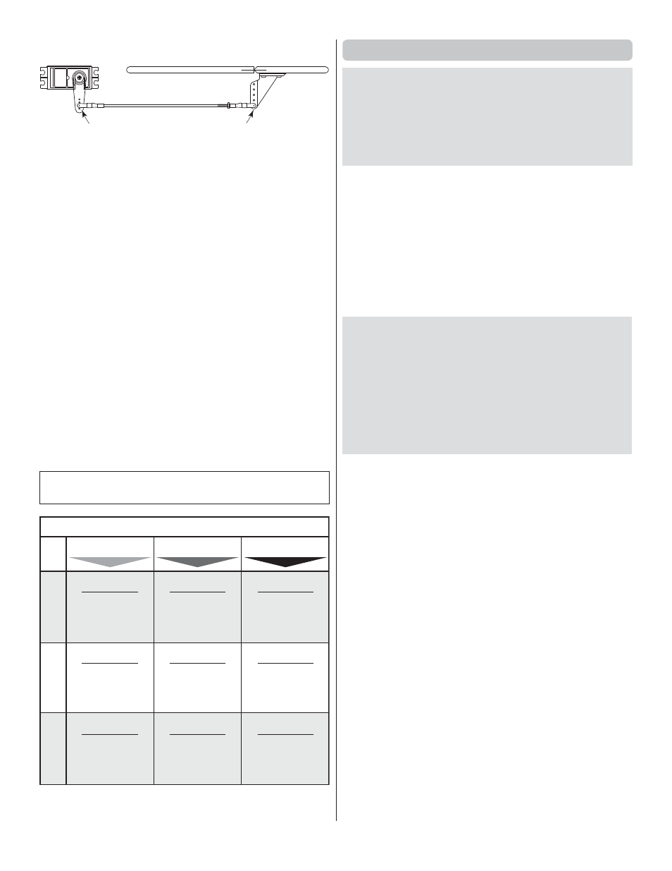
ACCEPTABLE PUSHROD HOOKUP
Move the pushrod farther out
on the servo arm…
…But leave the pushrod in the farthest out
location on the control horn.
If the optimum situation doesn’t provide enough control throw,
the pushrod may be moved inward on the control horn, but
it’s better to go
farther out
on the servo arm because this will
introduce less free play than the alternative. Only after moving
the pushrod all the way out on the servo arm, if you still can’t get
the throw required, you’ll have to resort to moving the pushrod
closer in on the control horn.
Note:
If you have a computer
radio, it is always desirable to set your ATVs to 100% (or as
near 100% as possible to achieve the control throw required).
If setting up a model that requires extraordinary control surface
throw (for 3D fl ying for example), start by “maxing-out” your
ATVs (typically 130% -- 140%). Then, the dual rates in your
“normal” fl ight mode will still be acceptably high (70% -- 80%)
for good servo resolution.
❏
4. Referring to the
Proper Pushrod Hookup
illustrations
above, adjust the location of the pushrod on the servo arm or on
the elevator horn and program the ATVs in your transmitter to
increase or decrease the throw according to the measurements
in the control throws chart.
❏
5. Measure and set the
low rate
elevator throws and the
high and low rate throws for the rest of the control surfaces
the same way.
NOTE
: The throws are measured at the
widest part
of the
elevators, rudder and ailerons.
These are the recommended control surface throws:
ELEV
A
T
OR
LOW RATE
3/4"
[19mm]
7°
Up & Down
3/4"
[19mm]
8°
Up & Down
4"
[102mm]
20°
Right & Left
R
UDDER
AILER
ONS
HIGH RATE
1-1/4"
[32mm]
12°
Up & Down
1-3/4"
[44mm]
19°
Up & Down
6"
[152mm]
42°
Right & Left
3D RATE
4"
[104mm]
42°
Up & Down
2-1/2"
[64mm]
27°
Up & Down
8"
[203mm]
63°
Right & Left
Balance the Model (C.G.)
More than any other factor, the C.G. (center of gravity/
balance point) can have the greatest effect on how a model
fl ies and could determine whether or not your fi rst fl ight will
be successful. If you value your model and wish to enjoy it
for many fl ights,
DO NOT OVERLOOK THIS IMPORTANT
PROCEDURE.
A model that is not properly balanced may
be unstable and possibly unfl yable.
At this stage the model should be in ready-to-fl y condition with
all
of the components in place including the complete radio
system, engine, muffl er, propeller, spinner and pilot. The fuel
tank should be empty.
❏
1. Use a fi ne-point felt tip pen to mark lines on the top of
wing on both sides of the fuselage 6.5" [165mm] back from
the leading edge. Apply narrow (1/16" [2mm]) strips of tape
over the lines so you will be able to feel them when lifting the
model with your fi ngers.
This is where your model should balance for the fi rst
fl ights. Later, you may experiment by shifting the C.G. 1/2"
[13mm] forward or 1/2" [13mm] back to change the fl ying
characteristics. Moving the C.G. forward will improve the
smoothness and stability, but the model will then be less
aerobatic (which may be fi ne for less-experienced pilots).
Moving the C.G. aft makes the model more maneuverable
and aerobatic for experienced pilots. In any case,
start at
the recommended balance point
and do not at any time
balance the model outside the specifi ed range.
❏
2. With the wing attached to the fuselage, all parts of the
model installed (ready to fl y) and an empty fuel tank, place
the model upside-down and lift it upside-down at the balance
point you marked.
❏
3. If the tail drops, the model is “tail heavy.” If possible, move
the battery pack and/or receiver forward to get the model to
balance. If the nose drops, the model is “nose heavy.” If possible,
move the battery pack and/or receiver aft. If needed, use Great
Planes “stick-on” lead (GPMQ4485). To fi nd out how much
weight is required, place incrementally increasing amounts
of weight on the fuselage over the location where it would be
mounted inside until the model balances. A good place to add
stick-on nose weight is to the fi rewall. Do not attach weight to
the cowl—this will cause the mounting screws to open up the
holes in the cowl. Once you have determined the amount of
weight required, it can be permanently attached. If required,
tail weight may be added by cutting open the bottom of the
fuse and gluing it permanently inside.
Note:
If mounting weight where it may be exposed to fuel
or exhaust, do not rely upon the adhesive on the back to
permanently hold it in place. Over time, fuel and exhaust
residue may soften the adhesive and cause the weight to fall
off. Instead, permanently attach the weight with glue or screws.