Complete the rudder control installation, Install the engine – Great Planes Yak-55M 50-55cc Sport / 3D ARF - GPMA1230 User Manual
Page 15
15
❏
❏
8. Use pliers to pull the cable from the fi rst loop to reduce
the size of the second loop. Squeeze the swage with pliers
and then cut off the excess wire. Do this for both wires.
❏
❏
9. Install a 4-40 thread clevis, 4-40 nut and a silicone
clevis keeper onto the threaded connectors.
❏
❏
10. Inside of the fuselage are two white plastic guide
tubes. Slide a wire into each of the tubes until they exit out the
fuselage sides. Connect the clevis to the hole in the aluminum
servo arm.
Note:
When you connect the clevises to the arm,
be sure that the wires cross each other. In other words, the
wire attached to the right side of the servo arm exits the left
side of the fuselage and the left side clevis exits out the right
side of the fuselage.
Complete the Rudder Control Installation
❏
1. Attach a clevis to the outer hole of the rudder control
horns that you modifi ed. Center the rudder and the rudder
servo. Attach the wire to each of the clevis assemblies and
then secure the wire with the swages using the same technique
used on the connection at the servo.
❏
2. Adjust the tension of the wires by turning the clevises in
or out on the connector. Then, lock the nut against the clevis.
Be sure to apply a drop of thread locker to the nut.
Install the Engine
The following instructions cover the installation of the DLE55.
Other engines will require similar installation. You will need to
determine the proper mounting hole positions and location for
the throttle connections for your choice of engine.
MOUNT THE ENGINE AND INSTALL THE THROTTLE
AND CHOKE SERVOS
The following instructions will show how to install a servo
activated choke. We know some modelers may wish to use
some sort of a manual linkage. It is recommended that you
read the installation instructions and then decide which method
you prefer. We will not be showing installation of a manual
linkage. Most modelers will fi nd that this is easy to do and
requires little explanation.
❏
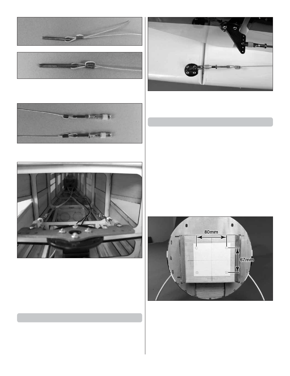
1. Locate the paper mounting pattern on page 32 of this
manual. Tape the pattern to the fi rewall, aligning the reference
lines on the paper pattern with the reference lines on the
fi rewall. When positioning it, the bolt hole pattern should be
aligned as shown.
❏
2. Drill a 1/8" [3.2mm] pilot hole through the center of each
mounting hole. Remove the paper pattern and drill a 13/64"
[5.2mm] hole through the fi rewall on each of the pilot holes