Great Planes Yak-55M 50-55cc Sport / 3D ARF - GPMA1230 User Manual
Page 13
13
❏
❏
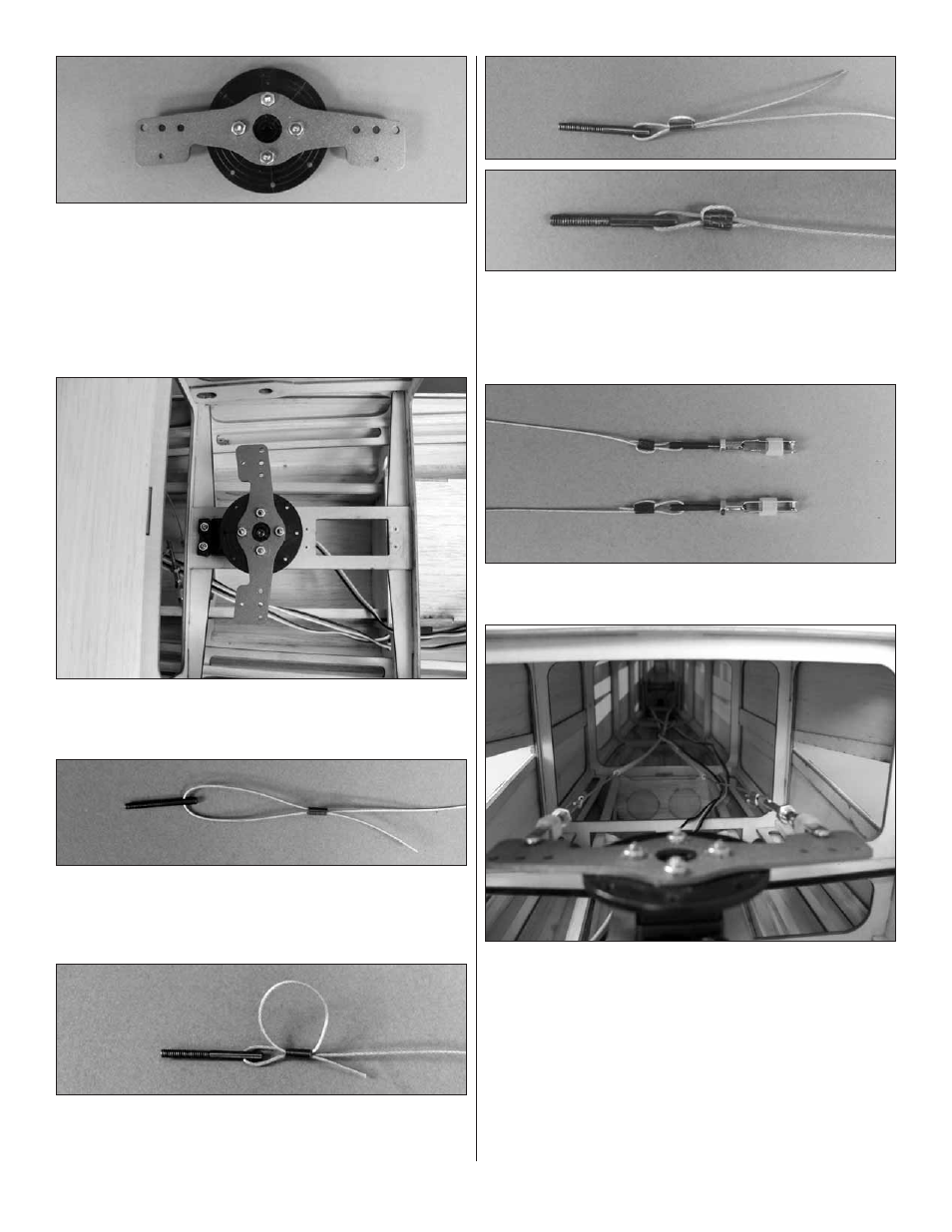
3. Position the aluminum servo arm on top of the disk.
Drill a 3/32" [2.4mm] hole through the aluminum arm and
through the disk. Do this for all four holes. Secure the arm to
the disk with four 2-56 x 1/2" [13mm] machine screws and
2-56 nuts. Be sure to secure the nuts with a drop of thread
locker. After the nuts are secure, cut off the thread from the
bolt that extends above the nut. This can be done with a high
speed motor tool or a good side cutter.
❏
❏
4. Install your servo into the rear rudder servo tray using
the hardware that came with your servo. Center the servo and
then install the servo arm.
❏
❏
5. Use wire cutters to cut the supplied braided cable into
two equal lengths. Slide a small tube (called a swage) over the
end of one cable. Then, guide the end of the cable through
the threaded brass coupler and the back through the swage.
❏
❏
6. Wrap the cable back around the swage and back
through the swage.
❏
❏
7. Use pliers to pull the cable from the fi rst loop to reduce
the size of the second loop. Squeeze the swage with pliers
and then cut off the excess wire.
❏
8. Repeat steps 2 – 7 for the remaining cable.
❏
9 Install a 4-40 thread clevis, 4-40 nut and a silicone clevis
keeper onto the threaded connectors.
❏
10. Inside of the fuselage are two white plastic guide tubes.
Slide a wire into each of the tubes until they exit out the
fuselage sides. Connect the clevis to the hole in the aluminum
servo arm.
Note:
When you connect the clevises to the arm
be sure that the wires cross each other. In other words, the
wire attached to the right side of the servo arm exits the left
side of the fuselage and the left side clevis exits out the right
side of the fuselage.
If you have completed the single servo installation, skip ahead
to, “Complete the Rudder Control Installation”.