Set the control throws, Proper pushrod hookup – Great Planes Yak-55M 50-55cc Sport / 3D ARF - GPMA1230 User Manual
Page 27
27
GET THE MODEL READY TO FLY
Check the Control Directions
❏
1. Turn on the transmitter and receiver and center the trims.
If necessary, remove the servo arms from the servos and
reposition them so they are centered. Reinstall the screws
that hold on the servo arms.
❏
2. With the transmitter and receiver still on, check all the
control surfaces to see if they are centered. If necessary, adjust
the clevises on the pushrods to center the control surfaces.
FULL
THROTTLE
RUDDER
MOVES
RIGHT
ELEVATOR
MOVES DOWN
RIGHT AILERON
MOVES UP
LEFT AILERON
MOVES DOWN
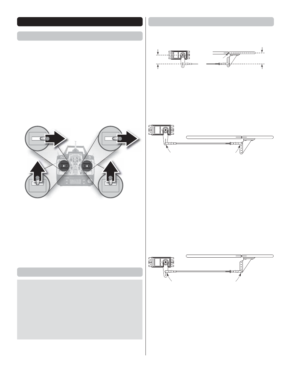
4-CHANNEL RADIO SETUP
(STANDARD MODE 2)
❏
3. Make certain that the control surfaces and the carburetor
respond in the correct direction as shown in the diagram. If any
of the controls respond in the wrong direction, use the servo
reversing in the transmitter to reverse the servos connected to
those controls. Be certain the control surfaces have remained
centered. Adjust if necessary.
Set the Control Throws
To ensure a successful fi rst fl ight, set up your Yak-55M
according to the control throws specifi ed in this manual.
The throws have been determined through actual fl ight
testing and accurate record-keeping, allowing the model
to perform in the manner in which it was intended. If, after
you have become accustomed to the way the Yak-55M fl ies,
you would like to change the throws to suit your taste, that
is fi ne. However, too much control throw could make the
model too responsive and diffi cult to control, so remember,
“more is not always better.”
Proper Pushrod Hookup
AVOIDING FLUTTER, MAXIMIZING
SERVO OUTPUT TORQUE
Pivot point
CONTROL
HORN OFFSET
SERVO ARM
OFFSET
When connecting pushrods and setting up your control throws,
it is
critically important
to use proper pushrod geometry—
that is the distance from the pushrod on the servo arm to the
center of the output shaft (
servo arm offset
) compared to
the distance from the pushrod on the control horn to the pivot
point (
control horn offset
).
EXTREMELY DANGEROUS PUSHROD HOOKUP
Pushrod far out
on the servo arm…
…pushrod close in
on the control horn.
One particularly dangerous situation arises when the pushrod
on the servo arm is too “far out” and the pushrod on the control
horn is too “close in.” This setup is usually chosen by pilots
who are trying to achieve maximum, “monster” control throws
for 3D fl ight. But with your pushrods set up this way, any free
play (slop) in the linkages or servo will be greatly magnifi ed,
possibly causing destructive control surface fl utter. Additionally,
if you have to turn your ATVs way down for “normal” throw,
the result will be poor resolution and poor servo holding/
centering capabilities. More importantly, too much force may
be transmitted back to the servo, possibly causing control
surface blowback, stripped servo gears or stripped servo
arms—the latter two likely causing a crash.
PREFERRED PUSHROD HOOKUP
“Closest in”
on servo arm
“Farthest out”
on control horn
Here is an
optimum pushrod setup—the pushrod is “close
in” on the servo arm and “far out” on the control horn. This
situation gives the greatest mechanical advantage of the
servo over the control surface, which will increase the servo’s
centering capabilities and output torque, minimize any free
play in the system and allow high ATV settings for optimum
servo resolution and positive control “feel.”
Note:
When the
pushrod is “close in” on the servo arm, make certain the servo
arm can travel through its full range of movement without the
pushrod (or clevis or other type of connector) interfering with
the servo arm, output shaft or servo case.