EVCO EV9326J9 User Manual
Page 3
Evco S.p.A. • Code 1049326E00 • page 3/6
5.2
Setting the cooking timer
• make sure that the instrument is in the on state, that the cooking timer
count is not in progress and that no procedure is in progress
• press
and
: the lower part of the display shows the value of
the cooking timer; the left part and the “timer”
LED will flash.
The value of the cooking timer is displayed in the hours:minutes for-
mat.
To modify the hour:
• press
or
within 15s
• press
: the right part will flash.
To modify the minutes:
• press
or
within 15s.
The cooking timer can be set between 00:00 and 24:00 h:min.
• press
: the “timer” LED will switch-off, after which the instru-
ment will exit the procedure.
To go back to previous levels:
• press
several times during the procedure.
To exit the procedure in advance:
• do not operate for 15s (any modifications will be saved).
The cooking timer can also be set when the count is in progress (this
modification is temporary, i.e. any power supply cut-off causes the
value set with the procedure given at the start of this paragraph to be
restored). If the value is set at 00:00 h:min, the count will be inter-
rupted, the “timer” LED will switch-off and the buzzer will be activated
for 3 seconds.
5.3
Starting the cooking timer
• press
during timer setting: the “timer” LED will switch on.
Alternatively:
• make sure that the instrument is in on state and that no procedure is
in progress
• press
: the “timer” LED will switch on.
5.4
Cooking timer start and switch-off of the instru-
ment on conclusion of the count
• make sure that the instrument is in on state and that no procedure is
in progress
• press
for 4s: the “timer” LED switches-on and the LED will
flash; the instrument will switch-off when the count has
been concluded.
5.5
Interrupting the cooking timer
• press
for 1s: the “timer” LED switches off and the buzzer will be
activated for 3s.
6
STEAM GENERATOR
6.1
Preliminary considerations
The steam generator allows to subordinate the steam injection to its
own state.
If functioning with 1 measurement input, if the steam probe is not
enabled, pressing the
and
keys for 1s will cause the steam
generator to switch on and successive pressing causes its switch-off;
steam injection is allowed on condition that the steam generator is on.
If functioning with 1 measurement input, if the steam probe is not
enabled, pressing the
and
keys for 1s will enable the steam
generator, after which the activity of the same will depend on the
temperature of the steam (steam probe), the steam set-point and pa-
rameter t3 (successive pressing of the keys causes the steam generator
to be disabled); steam injection is allowed on condition that the tem-
perature of the steam is above that established with the steam set-point
or at the minimum. Once the steam set-point has been reached, above
the “steam set-point - t4”.
If functioning with 2 measurement inputs, pressing the
and
keys for 1s will cause the steam generator to switch on and successive
pressing causes its switch-off; steam injection is allowed on condition
that the steam generator is on.
If the steam generator is not managed by any digital output , pressing
the
and
keys will cause the display of the “no” indication for
1s in the lower part of the display. In this case, steam injection is always
allowed.
7
STEAM INJECTION
7.1
Preliminary considerations
The functioning mode of the steam injection depends on parameter
t0.
If the parameter t0 is set at 0, pressing the
key causes the injection
of steam for the time established with parameter t2 or for the entire
duration that the key is pressed. The parameter t1 establishes the mini-
mum time that can pass between the two successive injections.
If the parameter t0 is set at 1, pressing the
key will enable the
automatic injection of the steam (in cyclical mode: parameter t2 estab-
lishes the duration of the injector switch-on and parameter t1 estab-
lishes the duration of switch-off).
Using the multifunction input, it is also possible to cause the same
effect caused by pressing the
key in remote mode.
Steam injection is subordinate to the steam generator state (see para-
graph 6.1).
7.2
Quick setting of the parameter t2
• make sure that the instrument is in on state and that no procedure is
in progress
• press
and
: the upper part of the display will show “t2”, the
lower part the corresponding value and the LED
will flash.
The parameter t2 can be set between 1 and 250 ds.
• press
or
within 15s
• press
: the LED will switch-off, after which the instrument will
exit the procedure.
To exit the procedure in advance:
• do not operate for 15s (any modifications will be saved).
7.3
Activation of the injector in manual mode (only if
parameter t0 is set at 0)
• make sure that the instrument is in on state and that no procedure is
in progress
• press
: the LED will switch-on and the injector will be acti-
vated, both for the time established with parameter t2 or
for the entire duration that the key is pressed.
The injector must not be deactivated in manual mode.
7.4
Enabling of automatic steam injection (only if pa-
rameter t0 is set at 1)
• make sure that the instrument is in on state and that no procedure is
in progress
• press
: the LED will switch-on and the injector will be acti-
vated in cyclical mode according to that established with
parameters t1 and t2 (until the key is pressed again).
8
AIRHOLE
8.1
Preliminary considerations
The airhole is activated in the following conditions:
• before the conclusion of the cooking timer count (of the time estab-
lished with the parameter c5), for the time established with param-
eter c6
• in manual mode, by pressing the
key for the time established
with parameter c7.
8.2
Quick setting of the parameter c7
• make sure that the instrument is in on state and that no procedure is
in progress
• press
and
: the upper part of the display will show “c7”, the
lower part the corresponding value the left part
and the LED will flash.
The parameter c7 is visualised in the minutes:seconds format.
To modify the minutes:
• press
or
within 15s
• press
: the right part will flash.
To modify the seconds:
• press
or
within 15s.
The parameter c7 can be set between 00:00 and 60:00 min:s.
• press
: the LED will switch-off, after which the instrument will
exit the procedure.
To go back to previous levels:
• press
several times during the procedure.
To exit the procedure in advance:
• do not operate for 15s (any modifications will be saved).
8.3
Activation of the airhole in manual mode
• make sure that the instrument is in on state and that no procedure is
in progress
• press
: the LED will switch on and the airhole will be acti-
vated, both for the time established with parameter c7.
8.4
Deactivation of the airhole in manual mode
• make sure no procedure is in progress
• press
: the LED will switch-off.
9
ECONOMY
9.1
Preliminary considerations
The economy allows to reduce the power supplied to the top and the
power supplied to the floor by switching an output on when the
other is off.
If functioning with 1 measurement input, when the function is in
progress the top output and the floor output are switched on for half
of the duration of the switch-on set using the procedure given in
paragraph 4.4 (intended as a percentage of the time established with
parameter c1).
If functioning with 2 measurement inputs, when the function is in
progress, the top output and the floor output are switched-on alter-
nately for half the time established with parameter c1.
When the time established with parameter c10 has passed, the func-
tion is interrupted.
Through the multifunction input it is also possible to activate the
economy function in remote mode.
If the rapid heating function is in progress, the economy function
cannot be activated.
9.2
Economy activation
• make sure that the instrument is in the on state, that no procedure is
in progress and no rapid heating function is in progress
• press
and
for 1s.
When the function is in progress the LED will flash for 1s every 4s.
9.3
Economy interruption in manual mode
• make sure no procedure is in progress
• press
and
for 1s.
10
RAPID HEATING (only if functioning with 1 meas-
urement input)
10.1 Preliminary considerations
The rapid heating allows to reach the work set-point as quickly as
possible, supplying 100% of the power both to the top and the floor
(i.e. excluding switch-on of the top and floor outputs in a cyclical way
with benefit to switch-on in continuous mode).
When the temperature of the chamber reaches the “work set-point -
temperature established with parameter c3” value, the function is in-
terrupted.
If the economy function is in progress, the rapid heating cannot be
activated.
10.2 Rapid heating activation
• causes the event established with parameter c2:
- if c2 = 1, press
for 1s (make sure that the instrument is in the on
state, that no procedure is in progress and the economy function is
not is progress)
- if c2 = 2, pass from the stand-by state to the on state
- if c2 = 3, press
for 1s (make sure that the instrument is in the on
state, that no procedure is in progress and the economy function is
not is progress) or pass from the stand-by state to the on state.
If parameter c2 is set at 0, the function cannot be activated.
When the function is in progress the upper part of the display shows
“F-F” alternately to the quantity established with parameter P5.
10.3 Interruption of rapid heating in manual mode
• make sure no procedure is in progress
• press
for 1s.
11
SIGNALS
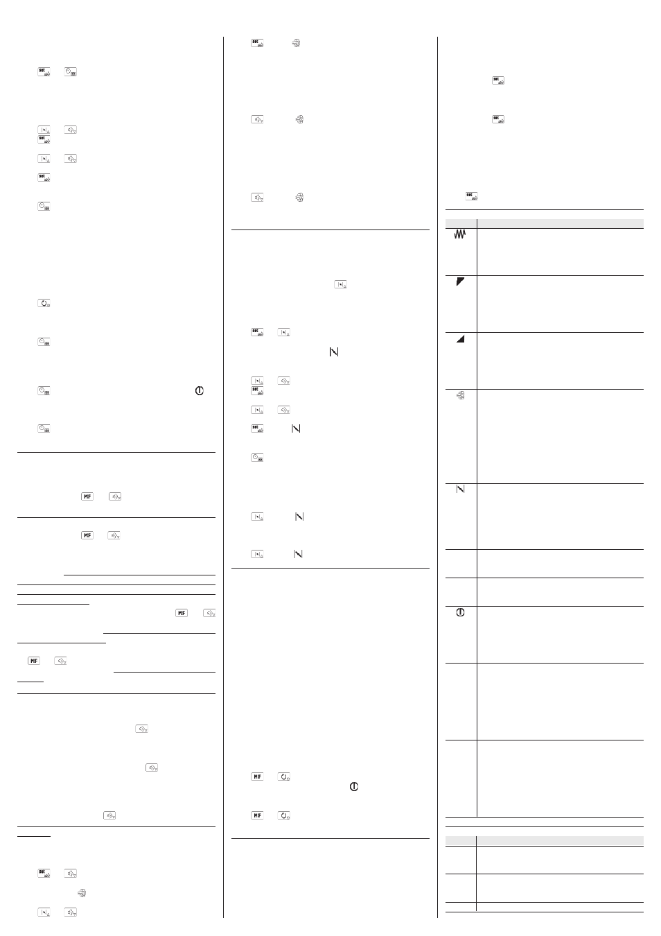
11.1 Signals
LED
MEANING
top and floor LED
if it is on, the to output and/or the floor output will be on
if it flashes, the modification of the work set-point, the top
set-point and the floor set-point is in progress (with the
procedures indicated in paragraphs 4.3.1 or 4.3.2)
power distributed to the top LED
supplies and indication regarding the power distributed
to the top
if it flashes, the modification of the power distributed to the
top is in progress (with the procedure indicated in para-
graph 4.4)
power distributed to the floor LED
supplies and indication regarding the power distributed
to the floor
if it flashes, the modification of the power distributed to the
floor is in progress (with the procedure indicated in para-
graph 4.4)
steam injection LED
if it is on:
• and the parameter t0 is set at 0, steam injection will be in
progress
• and the parameter t0 is set at 1, steam injection will be in
enabled
if it flashes:
• rapid setting of parameter t2 is in progress (see para-
graph 7.2)
• steam injection will not be available (parameter t4)
airhole LED
if it is on, the airhole will be activated in manual mode
if it flashes:
• the airhole will be activated due to the effect of the con-
clusion of the cooking timer count (parameter c6)
• rapid setting of parameter c7 is in progress (see para-
graph 8.2)
°
C
degrees Celsius LED
if it is on, the unit of measurement of the temperatures will
be degrees Celsius (parameterP2)
°
F
degrees Fahrenheit LED
if it is on, the unit of measurement of the temperatures will
be degrees Fahrenheit (parameter P2)
on/stand-by LED
if it is on, the instrument is in the stand-by state
if it flashes, the cooking timer count is in progress and on
conclusion of the count, the instrument will switch-off
if it flashes for 1s every 4s, the economy function will be in
progress
timer cooking timer LED
if it is on, the quantity shown by the lower part of the
display will be the value of the cooking timer or its count
if the timer will be activated
if it flashes:
• cooking timer setting is in progress
• the cooking timer count will be in progress but the lower
part of the display will be showing another quantity
set
set-point LED
if it is on, the quantity shown by the lower part of the
display will be the work set-point value, the top set-point
or the floor set-point
1
• the quantity displayed by the lower part of the display
will be the top set-point value
2
• the quantity displayed by the lower part of the display
will be the floor set-point value
12
INDICATIONS
12.1 Indications
INDICAT. MEANING
F-F
alternately to the quantity established with parameter P5:
the rapid heating function will be in progress (only if func-
tioning with 1 measurement input)
decrease the time established with parameter c9 is missing... 1 second
time
to the conclusion of the cooking timer count
c9
00:00 flashing: the cooking timer count has ended