Digilent Pegasus Board User Manual
Page 8
Pegasus Reference Manual
Digilent, Inc. ™
www.digilentinc.com
Page
8
Horizontal
Counter
Zero
Detect
3.84us
Detect
Horizontal
Synch
Set
Reset
T
S
T
disp
T
p
w
T
fp
T
bp
T
S
T
disp
T
p
w
T
fp
T
bp
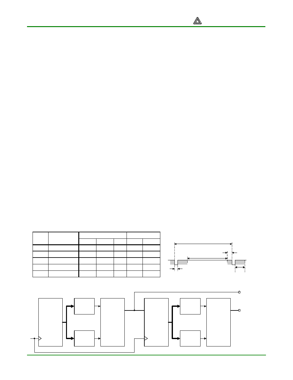
Sync pulse time
Display time
Pulse width
Front porch
Back porch
16.7ms
15.36ms
64 us
320 us
928 us
416,800
384,000
1,600
8,000
23,200
521
480
2
10
29
Symbol
Parameter
Time
Clocks
Lines
Vertical Sync
32 us
25.6 us
3.84 us
640 ns
1.92 us
800
640
96
16
48
Clocks
Horizontal Sync
Time
Vertical
Counter
Zero
Detect
64us
Detect
Vertical
Synch
Set
Reset
CE
VS
HS
from 240 to 1200 rows, and from 320 to 1600
columns. The overall size of a display, and the
number of rows and columns determines the
size of each pixel.
Video data typically comes from a video
refresh memory, with one or more bytes
assigned to each pixel location (the DIO4
board uses three bits per pixel). The controller
must index into video memory as the beams
move across the display, and retrieve and
apply video data to the display at precisely the
time the electron beam is moving across a
given pixel.
VGA System Timing
VGA signal timings are specified, published,
copyrighted, and sold by the VESA
organization (www.vesa.org). The following
VGA system timing information is provided as
an example of how a VGA monitor might be
driven in 640 by 480 mode. For more precise
information, or for information on higher VGA
frequencies, refer to the VESA website above.
A VGA controller circuit must generate the HS
and VS timing signals and coordinate the
delivery of video data based on the pixel clock.
The pixel clock defines the time available to
display one pixel of information. The VS signal
defines the “refresh” frequency of the display,
i.e., the frequency at which all information on
the display is redrawn. The minimum refresh
frequency is a function of the display’s phosphor
and electron beam intensity, with practical
refresh frequencies falling in the 50Hz to 120Hz
range.
The number of lines to be displayed at a given
refresh frequency defines the horizontal “retrace”
frequency. For a 640-pixel by 480-row display
using a 25MHz pixel clock and 60 +/-1Hz
refresh, the signal timings shown in the table
below can be derived. Timings for sync pulse
width and front and back porch intervals (porch
intervals are the pre- and post-sync pulse times
during which information cannot be displayed)
are based on observations taken from VGA
displays.
A VGA controller circuit decodes the output of a
horizontal-sync counter driven by the pixel clock
to generate HS signal timings. This counter can
be used to locate any pixel location on a given
row. Likewise, the output of a vertical-sync
counter that increments with each HS pulse can
be used to generate VS signal timings, and this
counter can be used to locate any given row.
These two continually running counters can be
used to form an address into video RAM. No
time relationship between the onset of the HS
pulse and the onset of the VS pulse is specified,
so the designer can arrange the counters to
easily form video RAM addresses, or to minimize