Digilent Pegasus Board User Manual
Page 6
Pegasus Reference Manual
Digilent, Inc. ™
www.digilentinc.com
Page
6
L
R
0
1 XS YS XY YY P
X0 X1 X2 X3 X4 X5 X6 X7 P
Y0 Y1 Y2 Y3 Y4 Y5 Y6 Y7 P
1
0
1
0
0
1
1
Idle state
Start bit
Stop bit
Start bit
Mouse status byte
X direction byte
Y direction byte
Stop bit
Start bit
Stop bit
Idle state
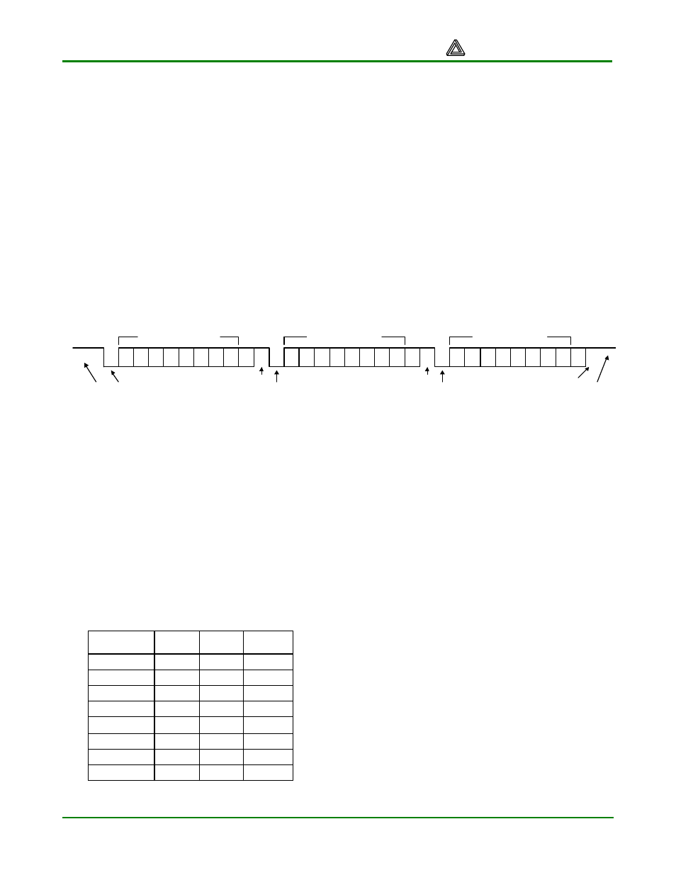
Figure 10. PS/2 mouse data
moved, three 11-bit words are sent from the
mouse to the host device. Each of the 11-bit
words contains a ‘0’ start bit, followed by eight
bits of data (LSB first), followed by an odd
parity bit, and terminated with a ‘1’ stop bit.
Thus, each data transmission contains 33 bits,
where bits 0, 11, and 22 are ‘0’ start bits, and
bits 10, 21, and 32 are ‘1’ stop bits. The three
8-bit data fields contain movement data as
shown below. Data is valid at the falling edge
of the clock, and the clock period is 20 to
30KHz.
The mouse assumes a relative coordinate
system wherein moving the mouse to the right
generates a positive number in the X field, and
moving to the left generates a negative
number. Likewise, moving the mouse up
generates a positive number in the Y field, and
moving down represents a negative number
(the XS and YS bits in the status byte are the
sign bits – a ‘1’ indicates a negative number).
The magnitude of the X and Y numbers
represent the rate of mouse movement – the
larger the number, the faster the mouse is
moving (the XV and YV bits in the status byte
are movement overflow indicators – a ‘1’
means overflow has occurred). If the mouse
moves continuously, the 33-bit transmissions
are repeated every 50ms or so. The L and R
fields in the status byte indicate left and right
button presses (a ‘1’ indicates the button is
being pressed).
VGA Port
The five standard VGA signals red (R), green
(G), blue (B), horizontal sync (HS), and vertical
ync (VS) are routed from FPGA pins to the
VGA connector. The color signals pass
through 270-ohm resistors on the Pegasus
board to create a resistor-divider with the 75-
ohm VGA cable termination. This limits the
voltage at the VGA connector to the specified
0V (fully-off) to 0.7V (fully-on) range. This
three-bit color system allows for eight different
colors as shown in the table.
Color
Red
Green
Blue
Black
0
0
0
Blue
0
0
1
Green
0
1
0
Cyan
0
1
1
Red
1
0
0
Purple
1
0
1
Yellow
1
1
0
White
1
1
1
Table 1. Three-bit color system
CRT Display Systems Background
Cathode ray tube (CRT)-based VGA displays
use amplitude-modulated, moving electron
beams (or cathode rays) to display information
on a phosphor-coated screen. LCD displays use
an array of switches that can impose a voltage
across a small amount of liquid crystal, thereby
changing light permittivity through the crystal on
a pixel-by-pixel basis. Although the following
description is limited to CRT displays, LCD
displays have evolved to use the same signal
timings as CRT displays (so the “signals”
discussion below pertains to both CRTs and
LCDs).
CRT displays use three electron beams (one for
red, one for blue, and one for green) to energize
the phosphor that coats the inner side of the
display end of a cathode ray tube (see drawing
below). Electron beams emanate from electron
guns, which are finely-pointed heated cathodes
placed in close proximity to a positively charged
annular plate called a “grid”.