Digilent Pegasus Board User Manual
Page 3
Pegasus Reference Manual
Digilent, Inc. ™
www.digilentinc.com
Page
3
The primary oscillator is connected to the
GLK1 input of the Spartan 2 (pin 77) and the
secondary oscillator is connected to GCLK2
(pin 182). Both clock inputs can drive a DLL on
the Spartan 2, allowing for a wide range if
internal frequencies are up to four times higher
than the external clock signals. Any 5V
oscillator in a half-size DIP package can be
loaded into the secondary oscillator socket.
Pushbuttons, Slide Switches, and LEDs
Four pushbuttons and eight slide switches are
provided for circuit inputs. Pushbutton inputs
are normally low, and they are driven high only
when the pushbutton is pressed. Slide
switches generate constant high or low inputs
depending on their position. Pushbutton inputs
use RC networks to provide nominal debounce
and ESD protection. Slide switch inputs use
only a series resistor for protection.
Eight LEDs are provided for circuit outputs.
LED anodes are driven directly from the FPGA
via 470-ohm resistors, and the cathodes are
connected directly to ground. A ninth LED is
provided as a power-on LED, and a tenth LED
indicates JTAG programming status.
390 ohms
From
FPGA
4.7K ohms
0.1uF
4.7K
ohms
3.3V
To FPGA
4.7K
ohms
To FPGA
3.3V
Pushbuttons
Slide switches
LEDs
Figure 3. Pushbutton, slide switch, and LED circuits
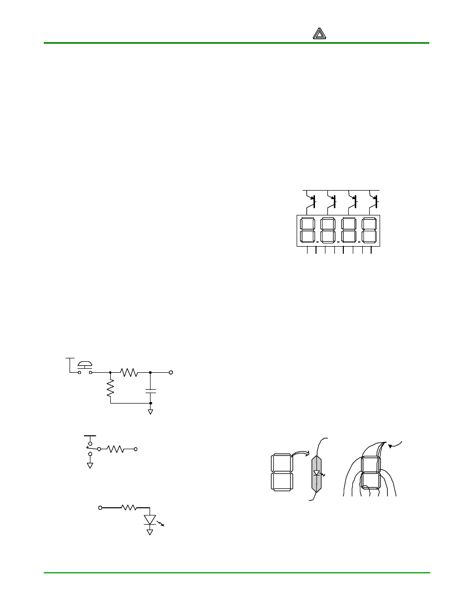
Seven-Segment Display
The Pegasus board contains a four-digit
common anode seven-segment LED display.
The display is multiplexed, so only seven
cathode signals exist to drive all 28 segments
in the display. Four digit-enable signals drive
the common anodes and these signals
determine which digit the cathode signals
illuminate.
Anodes are connected via
transistors for greater current
AN0
Vdd
a b c d e f
g dp
AN1
AN2
AN3
Cathodes are connected to
Xilinx device via 100
Ω
resistors
Figure 4. Common anode Sseg display
The seven anodes of each digit’s LEDs are
connected together into one “common anode”
circuit node. The display has four such nodes
named AN0 – AN3, and the signals that drive
these nodes serve as digit enablers. Driving an
anode signal low enables the corresponding
digit. The cathodes of similar segments on all
four displays are connected into seven circuit
nodes labeled CA through CG. Driving cathode
signals low illuminates segments on any digit
whose digit enable is low.
Common anode
a
f
e
d
c
b
g
a f g e d c b
Figure 5. Common anode detail
This connection scheme creates a multiplexed
display, where driving the anode signals and
corresponding cathode patterns of each digit in