Digilent Pegasus Board User Manual
Page 4
Pegasus Reference Manual
Digilent, Inc. ™
www.digilentinc.com
Page
4
a repeating, continuous succession can create
the appearance of a four-digit display. Each of
the four digits will appear bright and
continuously illuminated if the digit enable
signals are driven low once every 1 to 16ms
(for a refresh frequency of 1KHz to 60Hz). For
example, in a 60Hz refresh scheme, each digit
would be illuminated for one quarter of the
refresh cycle, or 4ms. The controller must
assure that the correct cathode pattern is
present when the corresponding anode signal
is driven.
AN0
AN1
AN2
AN3
Digit 0
Refresh period = 1ms to 16ms
Digit period = Refresh / 4
Digit 1
Digit 2
Digit 3
Figure 6. Sseg signal timing
To illustrate the process, if AN0 is driven low
while CB and CC are driven low, then a “1” will
be displayed in digit position 0. Then, if AN1 is
driven low while CA, CB and CC are driven
low, then a “7” will be displayed in digit position
1. If AN0 and CB, CC are driven low for 4 ms,
and then AN1 and CA, CB, CC are driven low
for 4 ms in an endless succession, the display
will show “71” in the rightmost two digits.
Digit
Cathode Signals
Shown
a b c d e f g
0
0 0 0 0 0 0 1
1
1 0 0 1 1 1 1
2
0 0 1 0 0 1 0
3
0 0 0 0 1 1 0
4
1 0 0 1 1 0 0
5
0 1 0 0 1 0 0
6
0 1 0 0 0 0 0
7
0 0 0 1 1 1 1
8
0 0 0 0 0 0 0
9
0 0 0 1 1 0 0
Figure 7. Cathode patterns for decimal digits
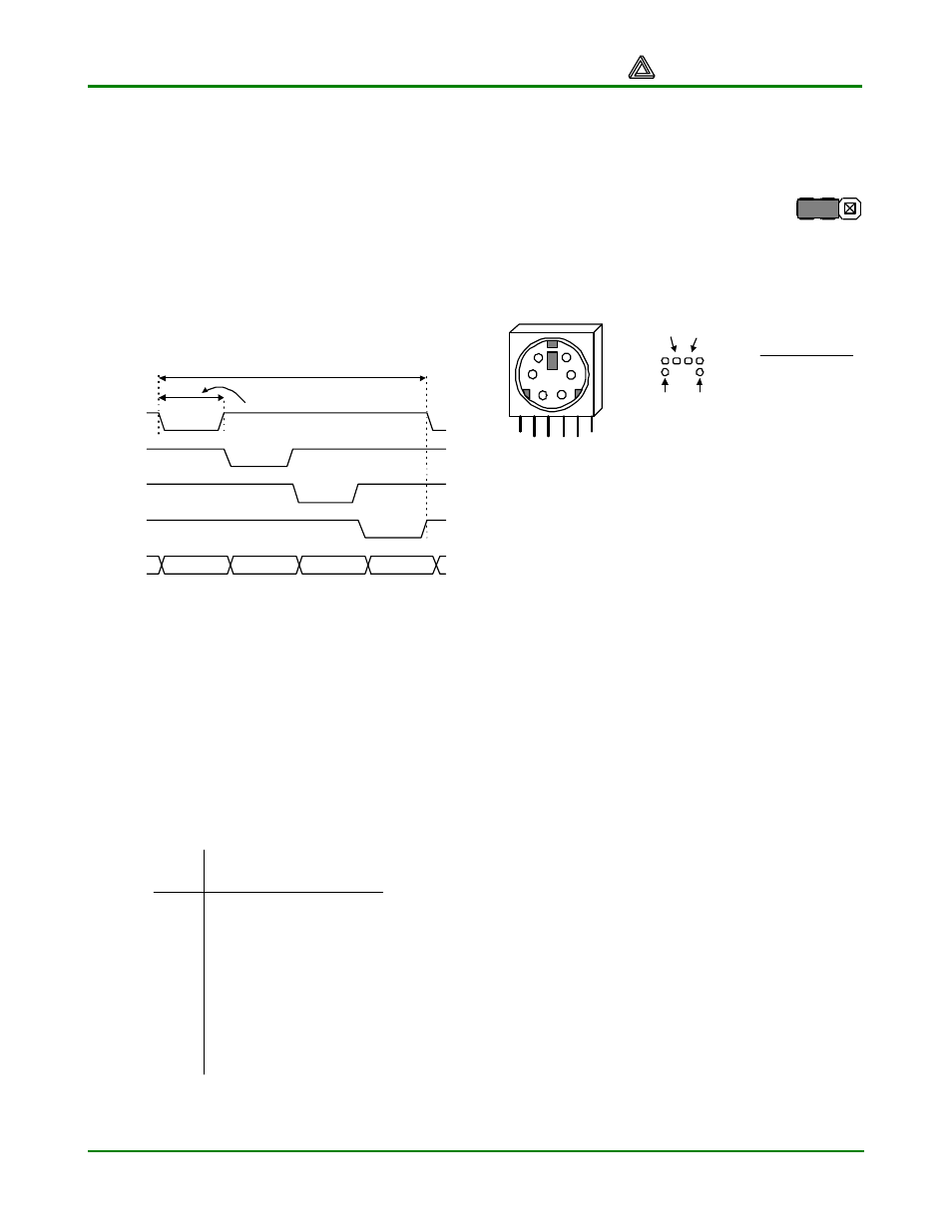
PS/2 Port
The Pegasus board includes a 6-pin mini-DIN
connector that can accommodate a PS/2
mouse or keyboard connection. A jumper on
the Pegasus board (J9) can be
loaded to provide 5V to the PS/2
port, or an external supply can be
connected to the “PS2VCC” pin of
J9 (some PS/2 devices require 5V
to work properly).
PS2 Connector
Pin 1
Pin 5
Pin 6
Bottom-up
hole pattern
Pin Definitions
Pin Function
1 Data
2 Reserved
3 GND
4 Vdd
5 Clock
6 Reserved
1
5
3
2
4
6
Pin 2
Figure 8. PS/2 connections
The PS/2 protocol uses a bi-directional two-
wire interface that includes a serial data and a
clock signal (the host-to-keyboard data
direction is used to send status LED data).
Driver circuits on both ends of the clock and
data signals use open-collector buffers with
10K pull-ups. The signals are only driven when
a key is actively pressed (or when the host is
actively sending LED status data). If the PS/2
device is only used as an input device, then
the host system can just use input buffers
(open-collector buffers are not required).
PS/2 mouse and keyboard devices use11-bit
data words that include a start bit, eight data
bits, and odd parity bit, and a stop bit. Data
timings are shown in the figure below. The
mouse and keyboard use eight-bit data
packets that are organized differently – the
keyboard sends eight-bit key scan codes, and
the mouse sends three eight-bit data elements
to define relative mouse movements.
Keyboard
Each key has a single, unique scan code that
is sent whenever the corresponding key is
pressed. If a key is continuously pressed for
more than 570ms, its scan code is repeated
each 104ms (but the time interval between first
and second transmission of the same code is
VCC33
PS2VCC
VU
J9
PS/2 Power