Digilent 6003-210-012P User Manual
Page 8
5
Signal Name
Pin
Voltage
Description
LED Rosetta 1
G16
any
West
LED Rosetta 2
G19
any
North
LED Rosetta 3
H17
any
East
LED Rosetta 4
G13
any
South
Table 4. FMC Connections for LEDs Adjacent to Push Buttons
5.
Rotary Push-button LED linear labeled ROT-1
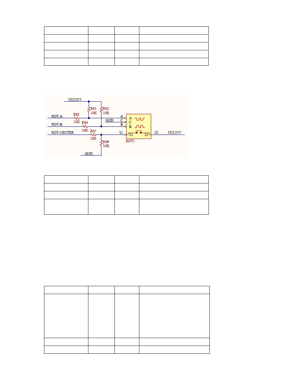
Figure 5. Rotary Switch Schematic
Signal Name
Pin
Voltage
Description
Rot-A
G21
2.5V
Reference waveform
Rot-B
H19
2.5V
Quadrature waveform
Rot-Switch
H20
2.5V
Activated by pressing the
knob
Table 5. Rotary Switch FMC Connections
6.
LCD (ST Micro ST7066) display with LVCMOS25 inputs. This dual row 16 character per row uses an
industry standard controller (Samsung KS0066U) and sports a 4 or 8 bit data interface. No backlight is
provided for the LCD, and the contrast if fixed.
This LCD supports 5x8 and 5x10 dot matrix characters and a programmable 4 or 8 bit MPU interface.
Support for custom characters is provided as is a wide range of instruction functions such as clear,
cursor home, display on/off, cursor shift, and display shift.
Signal Name
Pin
Voltage
Description
LCD Data 0
G22
2.5V
Four low order bi-directional
tristate data bus pins. Used for
data transfer and receive
between the MPU and the
ST7066.
These pins are not used during
4-bit operation.
LCD Data 1
H22
2.5V
As above
LCD Data 2
H23
2.5V
As above