Digilent 6003-210-012P User Manual
Page 5
2
4)
Rosetta pattern of 5 LEDs, co-located with the push button switches
5)
A Rotary/push-button switch
6)
An LCD display (2x16).
7)
Headphone jack (7a), speaker jack (7b) with a volume control (7c).
8)
4 SMA connectors
9)
2 Digilent dual PMOD connectors (9a), 1 Digilent single PMOD connector (9b)
Detailed Description
1.
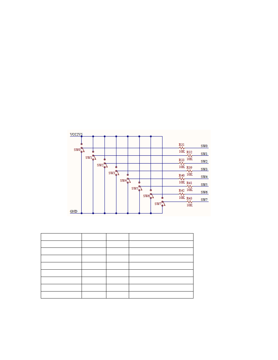
8 Slide switches: One side of each of the eight slide switches is tied to GND, while the other side is pulled
up to 2.5V. There is a 10K series resistor for each switch which enables these signals to be used at lower
voltages without damaging the FPGA. These switches are silkscreened SW0-SW7. SW0 is on the right
most side.
Figure 2. Slide Switch Schematics
Signal Name
Pin
Voltage
Description
Switch 0
G33
≤2.5V
Switch 1
H32
≤2.5V
Switch 2
H31
≤2.5V
Switch 3
G31
≤2.5V
Switch 4
G30
≤2.5V
Switch 5
H29
≤2.5V
Switch 6
H28
≤2.5V
Switch 7
G28
≤2.5V
Table 1. Slide Switch FMC connections
2.
There are 8 LED's in a linear fashion, co-located with the slide switches. Each is tied to GND through a
300 Ohm resistor. LD0 is on the right most side. The LEDs illuminate with voltages as low as LVCMOS12.