Digilent 6003-210-012P User Manual
Page 7
4
3.
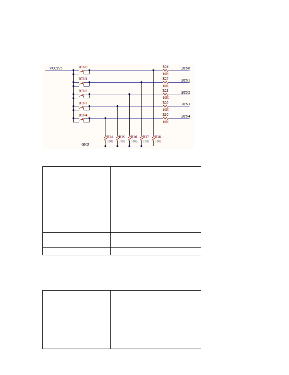
The 5 buttons are pulled to GND through a 10K resistor and pulled up to 2.5 V when pressed. When not
pressed the button is pulled up to 2.5V. A series resister (10K Ohms) bleeds off excess voltage if the
FPGA is programmed to an IO standard below 2.5V. These are marked BTN0-4.
Figure 4. Schematic for Buttons
Signal Name
Pin
Voltage
Description
Button 0
H14
2.5V
Center
Voltage must be sufficient to
cross the “on” threshold –
need to verify, as this might
be changed from “any” to >=
some voltage.
Button 1
G15
2.5V
West
Button 2
G18
2.5V
North
Button 3
H13
2.5V
East
Button 4
G12
2.5V
South
Table 3. Button FMC Connections
4.
Then there are 5 LED's co-located with the buttons (BTN0-BTN4) in a Rosetta pattern. Each LED is pulled
to GND via a 300 Ohm resistor. The schematics are show in (2) Linear LEDs
Signal Name
Pin
Voltage
Description
LED Rosetta 0
H16
any
Center
Voltage must be sufficient to
cross the “on” threshold –
need to verify, as this might
be changed from “any” to >=
some voltage.