Digilent 6003-210-012P User Manual
Page 10
7
Signal Name
Pin
Voltage
Description
Audio DAC sync right
G36
2.5V
Marks start of data frame
Table 7. Audio FMC Connections
8.
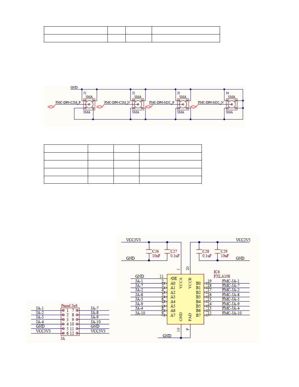
There are 4 SMA audio connectors J1 through J4. The silkscreen calls out the positive and negative sides
for Rx and Tx, however, these are straight through connections to the FMC, which allows the designer to
use them as he/she sees fit.
Figure 6. SMA Schematics
Signal Name
Pin
Voltage
Description
SMA-1
C2
any
J1 – north west
SMA-2
C3
any
J2 – north east
SMA-3
C6
any
J3 – south west
SMA-4
C7
any
J4 – south east
Table 8. SMA FMC Connections
9.
PMOD connectors: Two 12 pin “Dual” PMOD connectors are available on JA and JC, and a single 6 pin
PMOD is available on JB. These connectors are intended as connection points for Digilent's expansion
boards. The voltage, as always, represents the FPGA’s input and output voltage. There are voltage
translators on the FMC-CE card that translate the PMOD’s I/O to 3.3V.
Figure 7. PMOD Connector and Schematics