Installing the controller, Table 1-1. common switch settings (continued) – Comtrol API (6508) for the MS-DOS User Manual
Page 7
Installating RocketPort/ISA Systems
7
Installating RocketPort/ISA Systems
1.4. Installing the Controller
To prepare your controller for installation, you may need to set the
I/O
address
DIP
switch. The default
I/O
address range is 180 through 1C3. You must
change the
I/O
address settings on any additional controllers, even if you
select the default address range.
If you did not set the
DIP
switch on the controller or controllers during the
software installation, do so at this time. Make sure that you set each controller
as advised during the software installation or use the information in the
\ROCKET\INSTALL.LOG
file.
After you set the
I/O DIP
switch, you are ready to install the controller. Use the
following steps to install the controller:
1.
Turn the power switch for the system unit to the
OFF
position.
2.
Remove the system unit cover.
3.
Select a slot to install the controller.
4.
Remove the expansion slot cover.
5.
Insert the controller in the expansion slot, make sure that it is properly
seated.
6.
Attach the controller to the chassis with the expansion slot screw. Repeat
Steps 3 through 5 for each controller.
7.
Replace the cover on the system unit.
If connecting a system with an interface box:
a.
Attach the male end of the RocketPort cable to the controller and the
female end to the connector on the interface box labeled Host.
Note: If you have a RocketPort 32, the connector labelled J1 corresponds to
ports 0 through 15 on the interface box and the connector labeled J2
(closest to the bus) corresponds to ports 16 through 31.
b.
Connect the peripherals to the interface box.
Note: The ports on the interface box are numbered from 0 to 3, 7, or 15 on the
standard
DB25
interface. The Rack Mount RJ45 interface is numbered
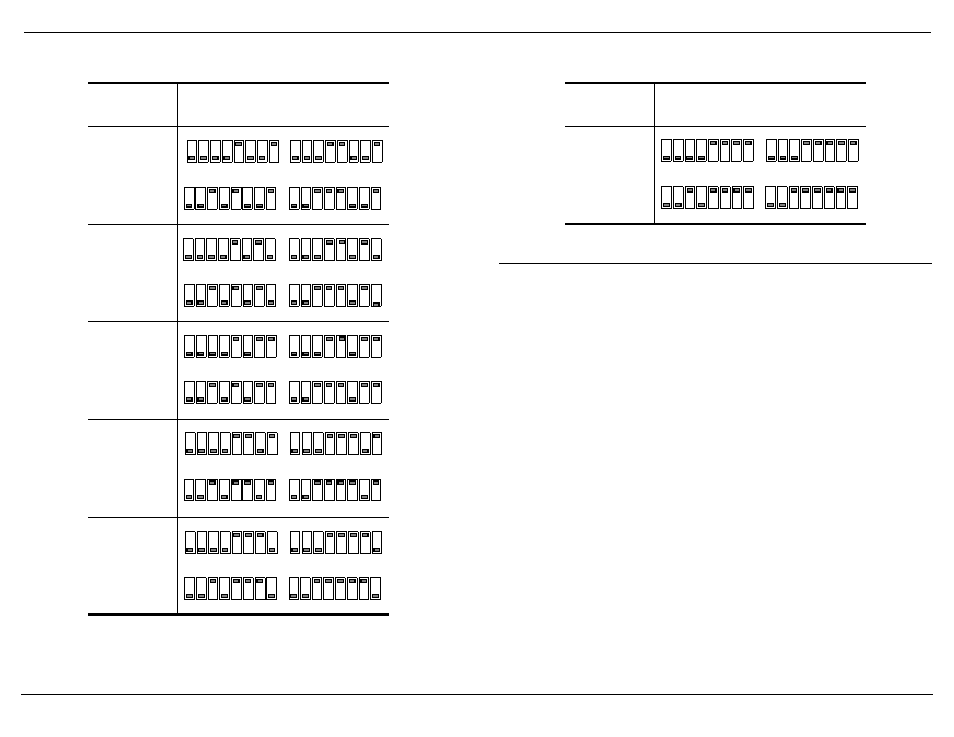
200 - 243 hex
240 - 283 hex
280 - 2C3 hex
300 - 343 hex
340 - 383 hex
Table 1-1. Common Switch Settings (Continued)
Controller
#1
I/O
Address
Range
DIP
Switch Settings
Controller #1 determines other
controller settings
1st ISA
2nd ISA
ON
1
2
3
4
5
6
7
8
ON
1
2
3
4
5
6
7
8
1
2
3
4
5
6
7
8
1
2
3
4
5
6
7
8
3rd ISA
4th ISA
1st ISA
2nd ISA
1
2
3
4
5
6
7
8
ON
1
2
3
4
5
6
7
8
ON
1
2
3
4
5
6
7
8
ON
1
2
3
4
5
6
7
8
3rd ISA
4th ISA
ON
1st ISA
2nd ISA
1
2
3
4
5
6
7
8
ON
1
2
3
4
5
6
7
8
ON
1
2
3
4
5
6
7
8
ON
1
2
3
4
5
6
7
8
3rd ISA
4th ISA
ON
1st ISA
2nd ISA
ON
1
2
3
4
5
6
7
8
ON
1
2
3
4
5
6
7
8
ON
1
2
3
4
5
6
7
8
ON
1
2
3
4
5
6
7
8
3rd ISA
4th ISA
1st ISA
2nd ISA
ON
1
2
3
4
5
6
7
8
ON
1
2
3
4
5
6
7
8
1
2
3
4
5
6
7
8
1
2
3
4
5
6
7
8
3rd ISA
4th ISA
380 - 3C3 hex
Table 1-1. Common Switch Settings (Continued)
Controller
#1
I/O
Address
Range
DIP
Switch Settings
Controller #1 determines other
controller settings
1st ISA
2nd ISA
ON
1
2
3
4
5
6
7
8
ON
1
2
3
4
5
6
7
8
ON
1
2
3
4
5
6
7
8
ON
1
2
3
4
5
6
7
8
3rd ISA
4th ISA