2. receiver operations – Kenwood TM-431E User Manual
Page 15
Attention! The text in this document has been recognized automatically. To view the original document, you can use the "Original mode".
(6) MR key
This key function just like the MR key on the front of the
radio.
(7)
PF (Programmable Function) key
This key can be programmed to perform any of the fol
lowing functions:
MHz key (Initial setting from the factory); or SHIFT key;
or TONE key; or REV key; or DRS key; or LOW key.
To program the key use the following procedure;
1. Turn the POWER switch on the transceiver OFF.
2.
Press and hold the key on the front panel of the
set
that
corresponds
with
the
function
you
wish
to program the microphone key to perform.
3.
Turn on the POWER switch while the key on the
front panel is held in.
4. Release the front panel key.
One
additional
function
can
be
programmed
that
is
not
included
on
the
front
panel
of
the
transceiver.
This
is
known
as
the
MONITOR
function.
This
will
allow
you
to
open
squelch
to
check
the
band
for
a
clear
frequency.
This will function even if you are operating in the CTCSS
decode
mode.
MONITOR
programming:
Press
and
hold
the F key on the front panel as you turn on the POWER
switch
of
the
transceiver
and
then
release
the
F
key.
® 16-Tone DTMF keypad (U.S.A. version only)
These buttons are used to activate the DTMF encoder.
See 4-6-4. for further information on their use.
® LOCK switch
This key will deactivate all functions of the microphone
except the PTT function and DTMF key pad.
4-2. RECEIVER OPERATIONS
Audio
confirmation
is
provided
whenever
a
front
panel
key
is
depressed.
You
can
disable
this
function
by
pressing
the
F
key
for
longer
than
1
second
and
then
pressing
the
REV/STEP key.
4-2-1. RECEPTION
1.
Connect the power supply, antenna, and microphone and
then adjust the controls as follows:
Power Switch
OFF
Vol Control
Full Counterclockwise
Power switch of power supply OFF
(Fixed station)
SQL Control
Full Counterclockwise
TM-431A
Fig. 1
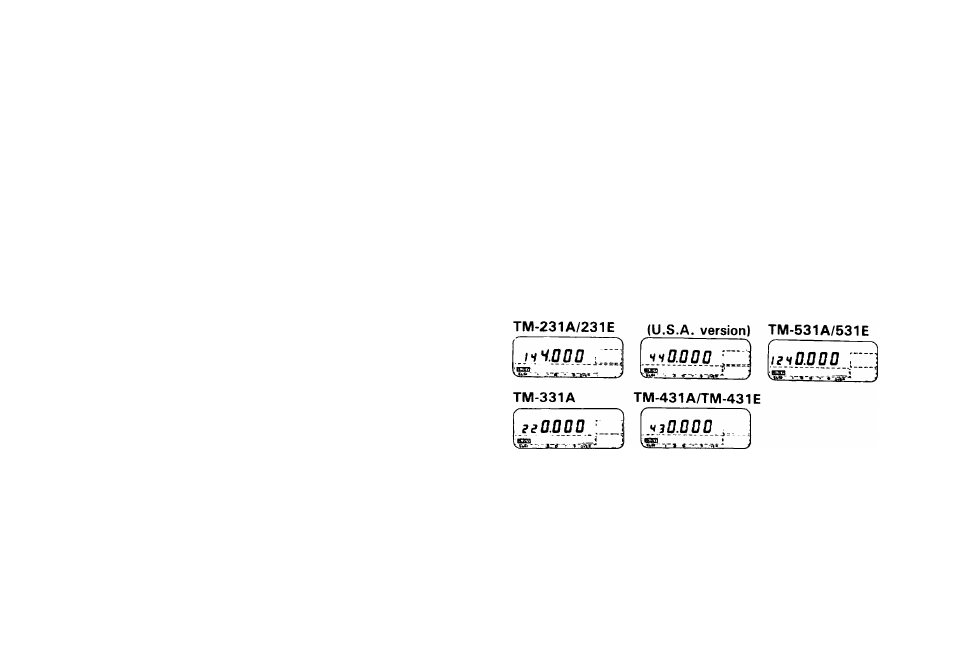
2.
Turn on the Power Supply and then turn on the tran
sceivers
POWER
switch.
The
display
should
indicate
a
frequency.
Fig.
1
shows
examples
of
frequencies
that
will appear on the various models. In addition to the fre
quency
you
may
see
one
or
more
control
indicator
turn
on in the display.
15