Kenwood TM-431E User Manual
Page 14
Attention! The text in this document has been recognized automatically. To view the original document, you can use the "Original mode".
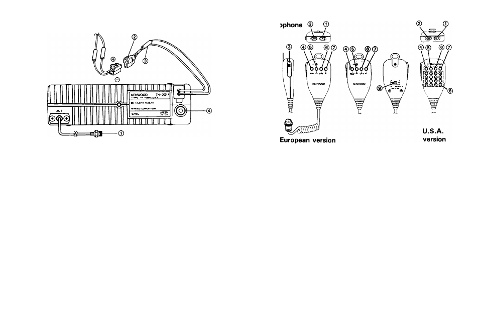
Rear Panel
© ANTENNA connector
Attach
an
antenna
with
a
low
SWR
and
impedance
of
50 ohms.
© 13.8 VDC power input connector
Connect
the
supplied
DC
power
cable
to
this
connector.
Pay
close
attention
to
the
polarity.
Red
is
positive
and
black is negative.
© Fuse holder
Contains one of the following fuse. Do not use a larger
fuse as damage might result to the transceiver.
TM-231A/231E : 15 A
TM-431A/431E : 10 A
TM-331A/TM-531A/531E : 8 A
0 External speaker jack
This
jack
is
used
to
connect
an
external
speaker.
The
speaker should have an impedance of 8 ohms.
14
© © UP/DWN switches
These switches can be used to increase or decrease the
VFO
frequency,
the
Memory
channel
number,
and
the
Tone frequency, etc..
@ PTT (Push to Talk) switch
The
transceiver
will
transmit
whenever
this
switch
is
depressed.
Scan
operations
may
be
cancelled
by
press
ing this switch without transmitting.
0 CALL key (except European version)
This
key
functions
just
like
the
CALL
key
on
the
front
of the radio.
1750 key (European version)
The
transceiver
will
transmit
with
1750
Hz
repeater
ac
cess tone whenever this switch is depressed.
© VFO key
This key functions just like the VFO key on the front of
the radio.