Introduction, Newer instruments, Appendix 7a manual status information – Fluke 2180A User Manual
Page 95
Attention! The text in this document has been recognized automatically. To view the original document, you can use the "Original mode".
2180A
Appendix 7A
Manual Status Information
INTRODUCTION
To identify the configuration of the pcb’s used in your
instrument, refer to the revision leter (marked in ink) on
the component side of each pcb assembly. Table 7A-1
defines the assembly revision levels documented in this
manual.
NEWER INSTRUMENTS
As changes and improvements are made to the
instrument, they are identified by incrementing the
revision letter marked on the affected pcb assembly.
These changes are documented on a supplemental
change/errata sheet which, when applicable, is inserted at
the front of the manual.
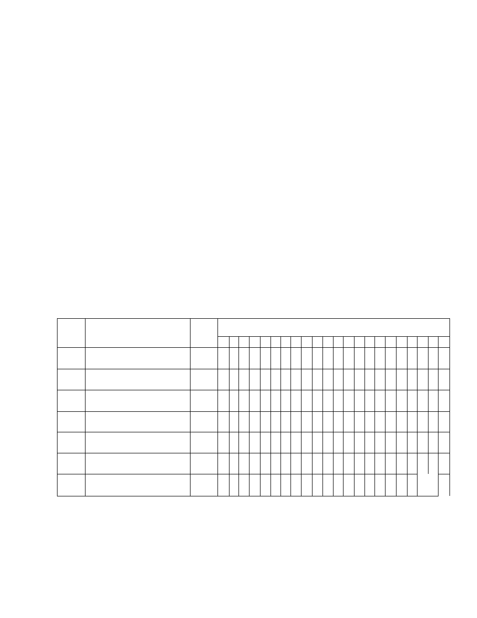
Table 7A>1. Manual Status and Backdating Information
Ref
Or
Option
No.
Assembly
Fluke
Part
PCB revision level documented in this manual.
Name
No.
-
A
в
с
D
Е
F
G
Н
J
К
L
М
N
р
A1
Main PCB Assembly
469312 •
•
•
+ + + + + -f
4-
+ +
X
A2
Display PCB Assembly
464297
X
A3
RTD PCB Assembly
469304 о •
•
X
-002
Output PCB Assembly
466144 •
О
+
+
+ + +
+ +
X
-004
IEEE-488 Interface PCB
Assembly
778456
0 + X
I
-CC6
Limits PCB Assembly
4о3135
О
О
о
о о
X
. -
I
X “ The PCS revision I
gvg
S
s
dc3umc;v:cd in this r.::
0= These revision letters irero
I n l \
+ = Caiicion nos
In
t":!s
—= Мэ revision letter on tt-e FOB.
7А-1/ 7A-2