9. input power, 11. cleaning, 13. fuse replacement – Fluke 2180A User Manual
Page 32: 15. service tools, 17. static discharge precautions, Input power -1, Cleaning -2, Fuse replacement -2, Service tools -2, Static discharge precautions -2
Attention! The text in this document has been recognized automatically. To view the original document, you can use the "Original mode".
2180A
4-9. Input Power
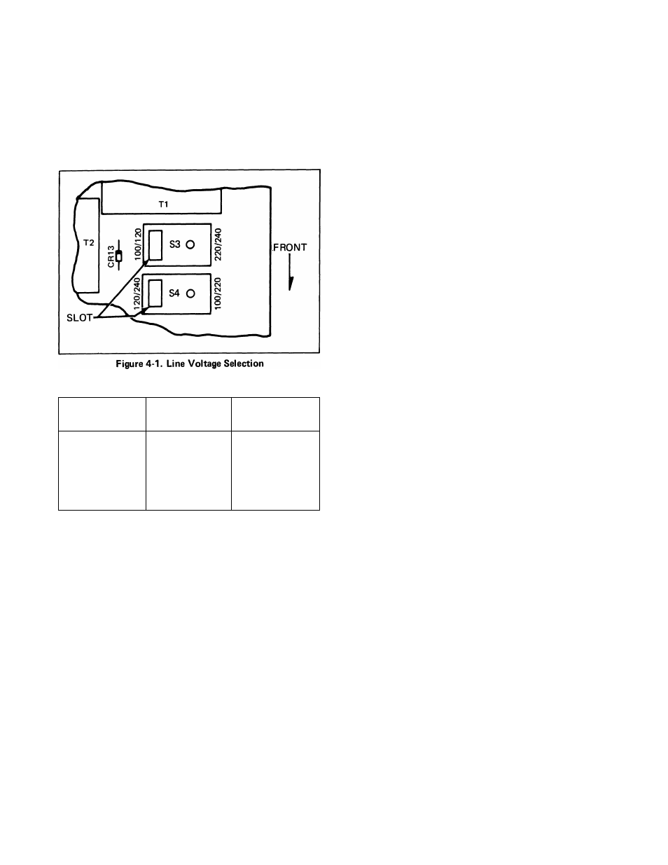
4-10. Input line power voltage is selected by positioning
the two switches on the right edge of the Main PCB. Each
switch (S3 and S4) has a position identifying slot; Figure
4-1, shows these slots positioned for 120V ac operation.
Table 4-1 lists the switch settings for other line voltages.
Table 4-1. Line Voltage Selection
VOLTAGE
S3 SLOT
(REAR SW)
S4 SLOT
(FRONTSW)
100
Left
Right
120
Left
Left
220
Right
Right
240
Right
Left
4-11. Cleaning
4-12. Clean the instrument periodically to remove dust,
grease and other contamination. Use the following
procedure:
CAUTION
Do not use aromatic hydrocarbons or
chlorinated solvents for cleaning. They will
react with plastic materials used In the
manufacture of the instrument.
1. Clean the front panel and case with a soft cloth
dampened with a mild solution of detergent and
water.
2. Clean the surface of the pcb using clean, dry air
at low pressure (^20 psi). If grease is encountered,
spray with Freon T.F. Degreaser or anhydrous
alcohol and remove grime with clean, dry air at low
pressure.
4-13. Fuse Replacement
WARNING
DISCONNECT
THE
UNIT
FROM
LINE
POWER
BEFORE
ATTEMPTING
FUSE
REPLACEMENT.
4-14. The 2180A has two fuses, both accessible on the
rear panel. FI is for the input line power and should be
replaced, when necessary, with a 1/8A MDL (slo-blo)
fuse when the input line power selected is lOOV or 120V.
When the input power selected is 220V or 240V, FI
should be replaced with a 1 / 16A MDL fuse. F2 is for the
12V dc external power and requires a 3/4A MDL fuse.
4-15. Service Tools
4-16. No special tools are required for maintenance or
repair.
4-17. Static Discharge Precautions
4-18.
Static
discharge
can
damage
components
contained in the 2180A. The following precautions
should be observed when conducting adjustments or
repairs with the instrument’s top cover removed.
1 Never conduct repairs without first pressing
power OFF, disconnecting the line cord and
accessory bus cable from the ACCESSORY
CONNECTOR.
2. Perform all repairs at a static-free work station.
3.
Minimize handling of ICs and the pcb; in no
case handle them by their connectors.
4.
Keep repair parts in their original container
until ready for use.
5.
Use static ground straps to discharge repair
personnel.
6.
Use conductive foam or anti-static containers
to store replacement or removed ICs.
7.
Remove all plastic, vinyl, and styrofoam
products from the work area.
8.
Do not slide static sensitive devices over any
surface.
9. Use only anti-static type solder removal tools.
10. Use grounded tip soldering irons.
4-2