19. performance test – Fluke 2180A User Manual
Page 33
Attention! The text in this document has been recognized automatically. To view the original document, you can use the "Original mode".
2180A
4-19. PERFORMANCE TEST
4-20.
The
Performance
Test
verifies
instrument
performance to specifications and may be used for initial
acceptance, verifying calibration, or as an aid in
troubleshooting. If the thermometer fails to meet
specifications either the Calibration Adjust Procedure or
Troubleshooting should be performed, as determined by
qualified service personnel.
11.
Verify that the 2180A reading is within the
tolerance listed in Table 4-3 (90-day or 1-year).
12. Repeat steps 9, 10, and 11 for the remaining
resistances listed for the RTD type being verified.
13. Repeat steps 9-12 for as many RTD types as
necessary.
4-21. Table 4-2 lists the equipment required for the Per
formance Test and Calibration Adjustment Procedure. If
the recommended model of test equipment is not available,
a substitute that meets the minimum use specifications may
be used. The test should be conducted with an ambient
temperature of 25 ± 5°C (73.4 ±9°F).
4-22.
Test:
Use the following procedure for the Performance
1. Set the POWER switch to OFF and remove the
line power cord from the line voltage source.
2.
On the RTD Input Module, position SI to 9
and S2 to AUTO.
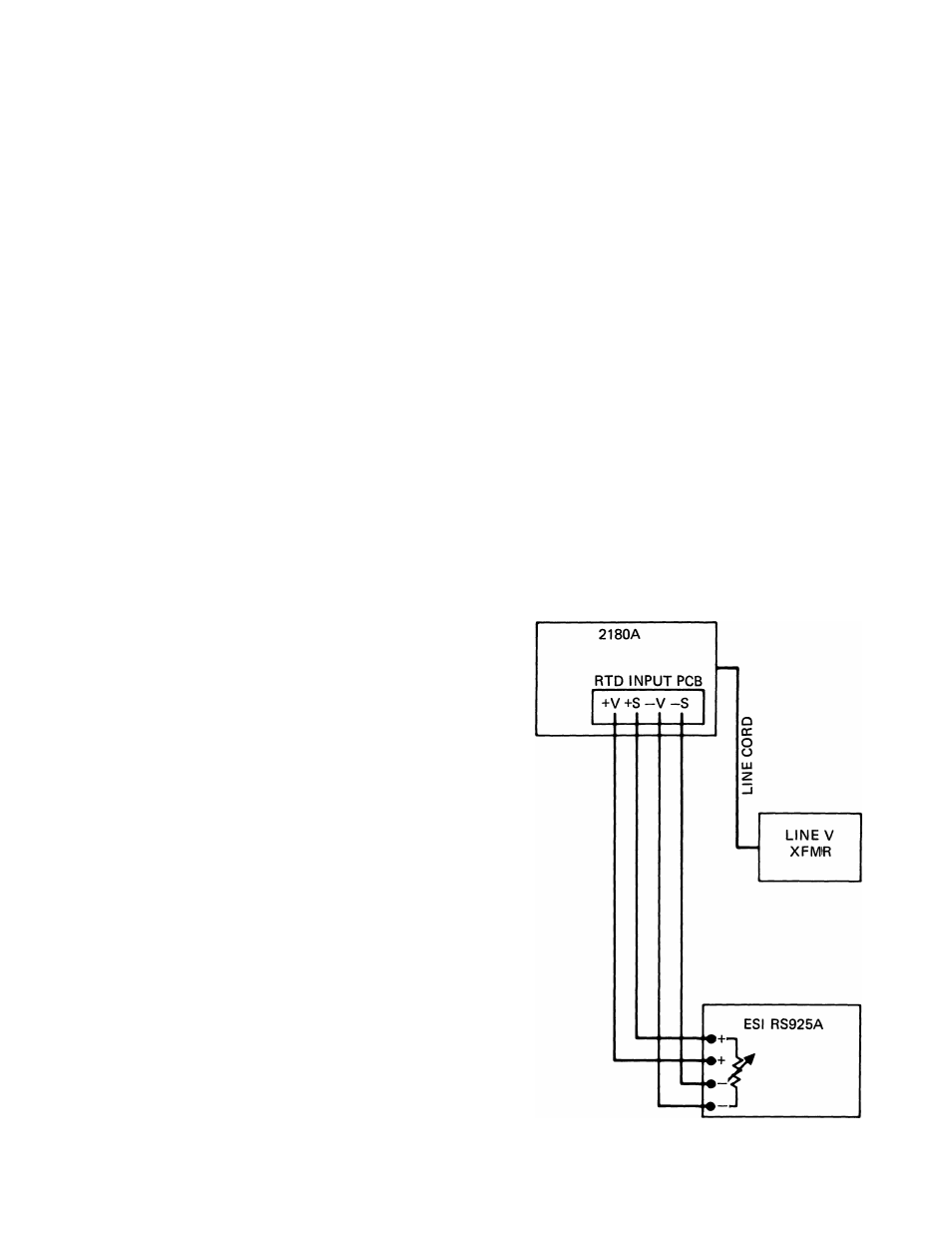
3. Connect the equipment as shown in Figure 4-2.
Refer to Table 4-2 for Recommended Test
Equipment.
4.
Verify the POWER switch is OFF, then adjust
the line voltage transformer for the nominal input
line voltage.
5. Set the POWER switch to ON.
6.
Allow the thermometer to stabilize (at least 20
minutes).
7. On the Decade Resistance Box, select lOO.OOil
and adjust R2 on the RTD Input Module for a
display of "51240" (equivalent to 0°C or 32° F).
8.
Refer to that portion of Table 4-3 pertaining to
the RTD(s) in use.
9.
On the Decade Resistance Box, select the first
resistance listed in Table 4-3 for the RTD type being
verified.
10.
On the RTD Input Module, set the selector
switch for the RTD type to be verified (0-5). Refer
to Table 2-2 for switch settings.
14.
Set the line voltage transformer for line
voltage minus ten percent and repeat the test for one
RTD type.
15.
Set the line voltage transformer for line
voltage plus ten percent and repeat the tests for one
RTD type.
16.
Set the line voltage transformer for the input
line voltage.
Figure 4-2. Performance Test Connections
4-3