Tpmc-ch-imc interface module, Crestron isys – Crestron electronic TPS-17B/W User Manual
Page 41
Crestron Isys
®
TPS-12B/W, TPS-15B/W & TPS-17B/W Tilt
Touchpanels
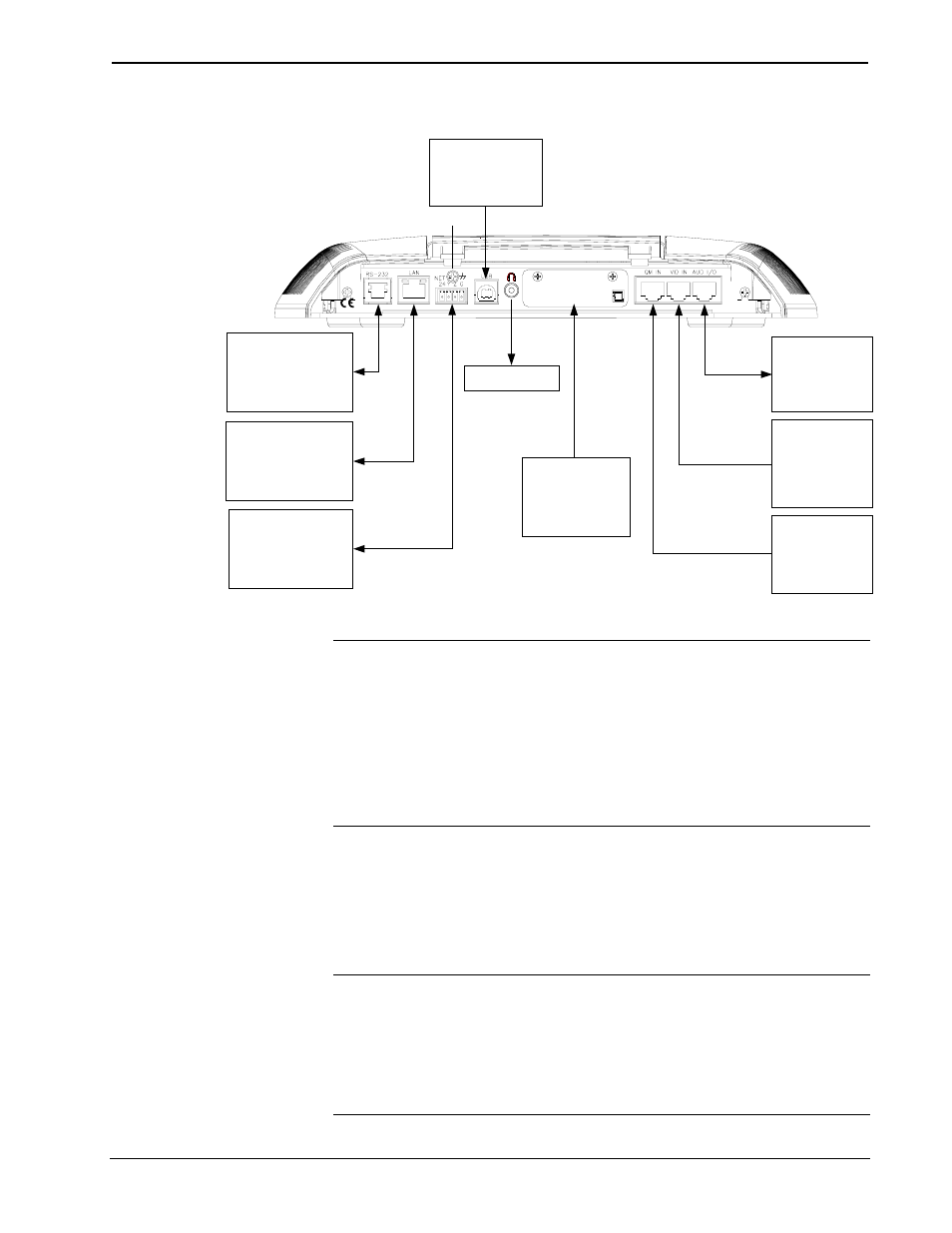
Hardware Connections for the TPS-12B/W, TPS-15B/W & TPS-17B/W
C E T
R S
ON
R
USB:
RESERVED FOR
FUTURE
APPLICATIONS
QM IN:
QUICKMEDIA
VIDEO, AUDIO
& MIC INPUT
OVER CAT5
AUDIO I/O:
BALANCED
AUDIO IN
& MIC OUT
OVER CAT5
HEADPHONES
COMPACT FLASH
CARDS
LAN:
10BaseT/100BaseTX
HIGH SPEED
ETHERNET TO LAN
RS-232:
TO COMPUTER OR
OTHER RS-232
DEVICE
GROUND
VIDEO IN:
BALANCED
VIDEO INPUT
OVER CAT5
NET:
TO CONTROL
SYSTEM AND
OTHER CRESNET
DEVICES
CAUTION: Only use the TPMC-CH-IMC Interface Module when connecting to the
VIDEO IN port. Use of older “IMC” products, such as those with a 10-pin RJ-45
based interface,
could damage the panel.
NOTE: A QuickMedia transmitter such as the QM-TX is required in order to
connect conventional video and audio sources to the QM IN port. The QM port is not
connected through any “IMC” interface.
NOTE: The connectors are not accessible after the rear cover is reinstalled.
TPMC-CH-IMC Interface Module
For networks without CAT5 audio and video, the TPMC-CH-IMC (as well as a
15-foot triamese interface cable) is included to convert unbalanced video sent over
coax cable and balanced/unbalanced audio sent over shielded, twisted-pair wiring to
Crestron Certified Wiring for connection to the touchpanels.
NOTE: The TPMC-CH-IMC is not for use with QuickMedia.
NOTE: Audio and video wiring between the touchpanel and module may be up to
500 feet for component video or 750 feet for composite and S-Video. However, the
length of Cresnet cable must account for limits based upon the touchpanel power
requirements. Refer to the latest version of the TPMC-CH-IMC Interface Module
Operations Guide (Doc. 6345) and “Network Wiring” on page 17.
Operations Guide – DOC. 6464A
Tilt Touchpanels: TPS-12B/W, TPS-15B/W & TPS-17B/W
• 37