Crestron isys – Crestron electronic TPS-17B/W User Manual
Page 17
Crestron Isys
®
TPS-12B/W, TPS-15B/W & TPS-17B/W Tilt
Touchpanels
Connectors, Controls & Indicators (Continued)
#
CONNECTORS
1
,
CONTROLS &
INDICATORS
DESCRIPTION
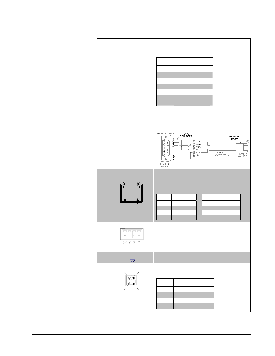
RS-232
(Continued)
PIN # DESCRIPTION
1
CTS
2
GND
3
RXD
4
TXD
5
RTS
6
N/C (Not
connected)
In the event that modular cables or an RJ-11 to DB9F
adapter is not available, the following diagram provides
information so that the cable can be fabricated on site.
(Alternatively, Crestron cable number STCP-502PC is
sold separately.)
3
LAN
GREEN
LED
YELLOW
LED
PIN 8
PIN 1
(1) 8-wire RJ-45 with two LED indicators;
10BaseT/100BaseTX Ethernet port;
Green LED indicates link status;
Yellow LED indicates Ethernet activity.
PIN
SIGNAL
PIN
SIGNAL
1
TX +
5
N/C
2
TX -
6
RC -
3
RC+
7
N/C
4
N/C
8
N/C
4
NET
Four-position terminal block connector for data
and power. Connects to Cresnet control network.
Pin 1 (24) Power
Pin 2 (Y) Data
Pin 3 (Z) Data
Pin 4 (G) Ground
5
G
(1) 6-32 screw, chassis ground lug.
6
USB
3
USB
Pin 2 Pin 1
Pin 3 Pin 4
(1) USB Type B female
(reserved for future applications)
PIN
DESCRIPTION
1
+5 VDC
2
Data -
3
Data +
4
Ground
(Continued on following page)
Operations Guide – DOC. 6464A
Tilt Touchpanels: TPS-12B/W, TPS-15B/W & TPS-17B/W
• 13