Tilt touchpanels crestron isys – Crestron electronic TPS-17B/W User Manual
Page 16
Tilt Touchpanels
Crestron Isys
®
TPS-12B/W, TPS-15B/W & TPS-17B/W
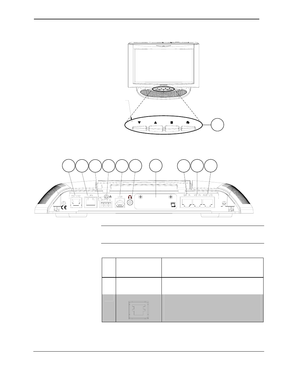
TPS-12B/W, TPS-15B/W & TPS-17B/W Pushbuttons
Reset Button
1
TPS-12B/W, TPS-15B/W & TPS-17B/W Connectors (Cover Removed)
C E T
R S
ON
R
2
3
4
5
6
7
8
9
11
10
NOTE: All connections to the TPS-12B/W, TPS-15B/W & TPS-17B/W are made
through the ports on the rear panel. These ports are not accessible after the cover is
replaced.
Connectors, Controls & Indicators
#
CONNECTORS
1
,
CONTROLS &
INDICATORS
DESCRIPTION
1 BUTTONS
2
(4) Backlit “softkey” buttons, programmable
(1) Backlit hard reset button, reboots the
touchpanel.
2
RS-232
(1) 6-pin RJ-11 female;
Computer console, touch output or mouse/touch
input port;
Bidirectional RS-232 up to 115.2k baud;
Hardware and software handshaking support.
(Continued on following page)
12
• Tilt Touchpanels: TPS-12B/W, TPS-15B/W & TPS-17B/W
Operations Guide – DOC. 6464A