2) system serial communication, Pdr-04 – Pioneer PDR-04 User Manual
Page 86
Attention! The text in this document has been recognized automatically. To view the original document, you can use the "Original mode".
PDR-04
(2) System serial communication
The mode controller performed serial communication between
the mechanism controller and LC89585 (digital interface LSI)
and PDC020A (FS converter LSI).
The mechanism controller also performed communication
with LC89585 at the following timings.
© Communication request from mechanism controller.
® Mechanism/mode controller communication
© Communication with mode controUer/LC89585
During this time, XFUSE is set to L and serial communi
cation of mechanism controll» is disabled.
0 Serial communication with mode controller/LM1972M
© Conununication with mechanism controller/LC89585
BUS
XFUSE
MREQ,
MACK
LREQ
AATLAT
ATIP
Standby
Mechanism
Mode
Mode
LC89585, LM1972M
Mecha.
LC89585
Standby
1® r
uinrinf
"LJ"
®
uir
~IS
■U
Approx. 13.3 mS
(3) Communication with Mechanism Controiier and
Mode Controiier
Communication Format
This CPU and the mechanism control CPU performed serial
conununication with 5 signal lines.
Mechanism
control
CPU
MSCK
FSCK
MSI
-
FSO
MSO
-
FSI
MREQ
-
MREQ
MACK
-
MACK
Mode control
CPU
• FSCK...........................Serial transmission clock (1 MHz)
• FSI/FSO....................... Serial data transmission line
• MREQ/M ACK Handshake line
The communication timing is control by the mechanism
control CPU. 13 byte data is transmitted every 13.33 to 40
ms. (Average:13.33 msec)
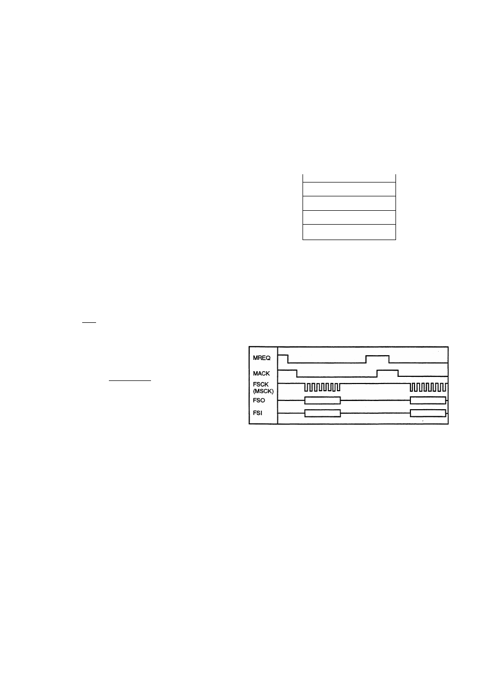
Conununication is performed by the following procedure.
© The MREQ signal becomes L as communication request
from the mechanism control microprocessor.
® This microprocessor sets the MACK signal to L as commu
nication enable signal.
© The mechanism controller sets the MREQ signal to H
after 1 byte serial transmission.
®
This microprocessor sets MACK to H if serial transmis
sion has ended normally.
© Hereafter © to © are repeated until the 13 byte data
transmission has completed.
^ The mechanism controller and mode controller observes
the state of the other side’s control line, and stops cormnu-
nication processing of transmission if conditions are not
satisfied after a certain time.
86