5 dpp (tracking offset) adjustment, Pdr-04 – Pioneer PDR-04 User Manual
Page 54
Attention! The text in this document has been recognized automatically. To view the original document, you can use the "Original mode".
PDR-04
Adjustment 1
[ How to find the null point ]
When you insert the small screwdriver into the slit for the grating adjustment and change the grating angle, the amplitude of
the tracking error signal at CN104 (TP1), Pin 3 (TE) changes. Within the range for the grating, there are five or six locations
where the amplitude of the wave reaches a minimum. Of these five or six locations, there is only one at which the envelope
of the waveform is smooth. This location is where the three laser beams divided by the grating are all right above the same
track. (See Fig. 4.)
This point is called the null point. When adjusting the grating, this null point is found and used as the reference position.
Turning the grating counterciockwise
Tuming the grating clockwise
Grating adjustment position
ms
.
\
/
Null point
Waveform of
CN104 (TP1), Pin 3 (TE)
mmmmmm
Null point waveform Maximum amplitude Wavefonn other than the
wavefonn
null point
Note: If the difference between the amplitude of the error signal at the
innemnost edge and outermost edge of the disc is more than 10%,
adjust the grating again.
Fig. 4
6.2.5 DPP (Tracking Offset) Adjustment
Adjustment 1
• Objective
• Symptom when out
of adjustment
To correct for the variation in the sensitivity of the tracking photodiode.
Play does not playback, track search is impossible, tracks are skipped.
• Measurement instru
ment connections
Connect the oscilloscope to
CN104(TP1), Pin3 (TE)
[This connection may be via a low
pass filter. (15k£2 + O.OOlpF) ]
[ Settings ]
50 mV/div.
5 mS/div.
DC mode
• Player state
• Adjustment
location
• Disc
Test mode,focus and spindle servos
closed and tracking servo open.
VR112(TE. OFS)
(HEAD BOARD assy)
STD-903
[ Procedure ]
(1 ) Move the pickup to the midway across the disc (R = 35mm) with the MANUAL / TRACK SEARCH FWD ►► or REV
MM
keys.
(2) Press the FINALIZE key, then the PLAY ► key in that order to close the focus servo then spindle servo.
(3) Line up the bright line (ground) at the center of the oscilloscope screen and put the oscilloscope into DC mode.
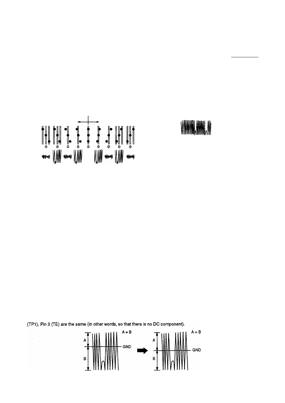
(4) Adjust VR112 (TE. OFS) so that the positive amplitude and negative amplitude of the tracking error signal at CN104
When there is a DC
component
When there is no DC
component
54