3 efm rising edge time adjustment, Pdr-04 – Pioneer PDR-04 User Manual
Page 58
Attention! The text in this document has been recognized automatically. To view the original document, you can use the "Original mode".
PDR-04
6.3.2 Multi Pulse Time Adjustment
Adjustment 2
• Objective
• Symptom when out
of adjustment
Pulse adjustment for recording (1)
Player does not playback CD-R discs which was recorded with this player.
• Measurement instru
ment connections
Connect the oscilloscope to
CN3506, Pin 6 (MPLS).
(STRATEGY SMALL BOARD assy)
[ Settings ]
1 mV/div.
20 nS/div.
DC mode
• Player state
• Adjustment
location
• Disc
Test mode, stop
VR3501 (MPLS DLY)
(STRATEGY SMALL BOARD assy)
None needed
[ Procedure ]
(1) Disconnect a connector CN3502.
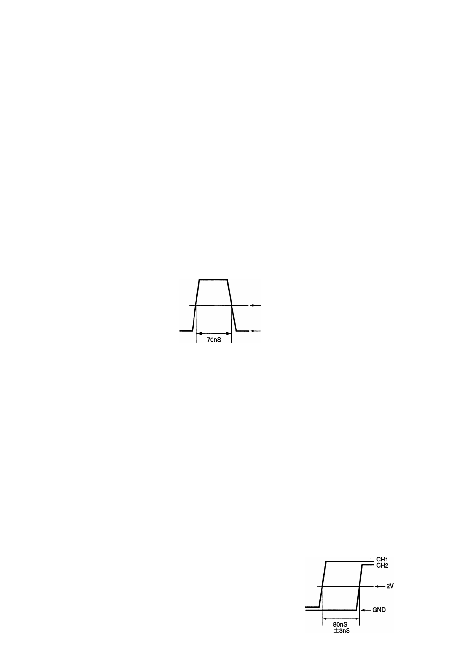
(2) Adjust the time from rising edge to falling edge of Waveform with 2V level.
(3) Adjust VR3501 (MPLS DLY) so that the DC voltage at CN3506 pin 6 (MPLS) becomes 70nS ± 3nS.
±3nS
2V
GND
6.3.3 EFM Rising Edge Time Adjustment
Adjustment 2
» Objective
> Symptom when out
of adjustment
Pulse adjustment for recording (2)
Player does not playback CD-R discs which was recorded with this player.
» Measurement instru
ment connections
Connect the oscilloscope to
CHI : CN3506, Pin 5 (EFM IN).
CH2 : CN3506, Pin 4 (SEFM).
(STRATEGY SMALL BOARD assy)
[ Settings ]
CHI : 1 V/dIv. DC mode
20 nS/div.
CH2 :1 V/div. DC mode
• Player state
• Adjustment
location
• Disc
Test mode, recording
power ON
VR3502 (EFM DLY)
(STRATEGY SMALL BOARD assy)
None needed
[ Procedure ]
(1) Disconnect a connector CN3502.
(2) Turn VR104 (REC. PW) fully counterclockwise to reduce the power is minimum.
(3) Press REC O and REC MUTE O keys in this order to lights up the laser diode.
(4) Adjust the time from rising edge of CN3506 pin 5 to rising edge of pin 4 of waveform with 2V level
(5) Adjust VR3502 (EFM DLY) so that the DC voltage becomes 80nS ± 3nS.
58