8) timing chart, Pdr-04 – Pioneer PDR-04 User Manual
Page 80
Attention! The text in this document has been recognized automatically. To view the original document, you can use the "Original mode".
PDR-04
(8) Timing Chart
(D Timing Chart when Power ON (Outlet ON)
POWER (IN)
XRST (IN)
XPFAIL (IN)
RAME
XSVRST
MACK (IN)
XTALOFF
1
)
2)
3)
4)
5)
1) Power turns on.
2) XRST becomes H and reset is turned off.
3) After reset is turned off, wait for XPFAIL to become H.
4) After XPFAIL becomes H, the microprocessor starts.
RAME becomes H, and the external SRAM is set to the enable state.
5) XSVRST becomes H, and servo circuit operations start.
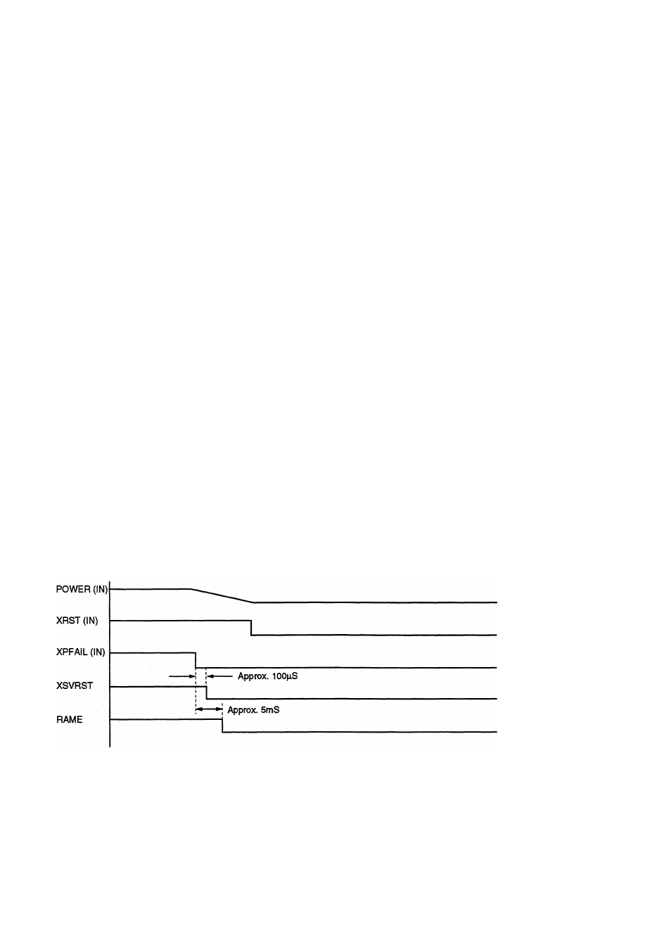
(2) Timing Chart when Power Failure
1) The power starts dropping and after a certain point, XPFAIL becomes L.
2) When XPFAIL becomes L, an internal interrupt is imposed, and the current operation mode and disc data are backed up.
3) At the same time, XSVRST becomes L, servo is reset, RAME is set to L, and the external SRAM is set to the disable state.
4) XRST then becomes L, and reset is set.
Note : If XRST becomes L first before RAME becomes L, the value of the backup RAM (IC352) will not be stored properly.
80