Pdr-04 – Pioneer PDR-04 User Manual
Page 62
Attention! The text in this document has been recognized automatically. To view the original document, you can use the "Original mode".
PDR-04
6.3.11 Tracking Offset Adjustment
Adjustment 2
• Objective
• Symptom when out
of adjustment
To correct for the variation in the sensitivity of the tracking photodiode.
Player does not playback, track search is impossible, tracks are skipped.
• Measurement instru
ment connections
Connect the oscilloscope to
CN104 (TP1), Pin3(TE).
[ This connection must be via a low
pass filter (15kQ + 0.001 p,F).]
[Settings] 20 mV/div.
5 mS/div.
DC mode
• Player state
• Adjustment
location
• Disc
Test mode, focus and spindle servos
closed and tracking servo open.
VR112(TE. OFS)
(HEAD BOARD assy)
STD-903
[ Procedure ]
(1 ) Move the pickup to midway across the disc (R = 35mm) with the MANUAL / TRACK SEARCH FWD ►► or REV
◄◄ keys.
(2) Press the FINALIZE key, then the PLAY ► key in that order to close the focus servo then the spindle servo.
(3) Line up the bright line (ground) at the center of the oscilloscope screen and put the oscilloscope into DC mode.
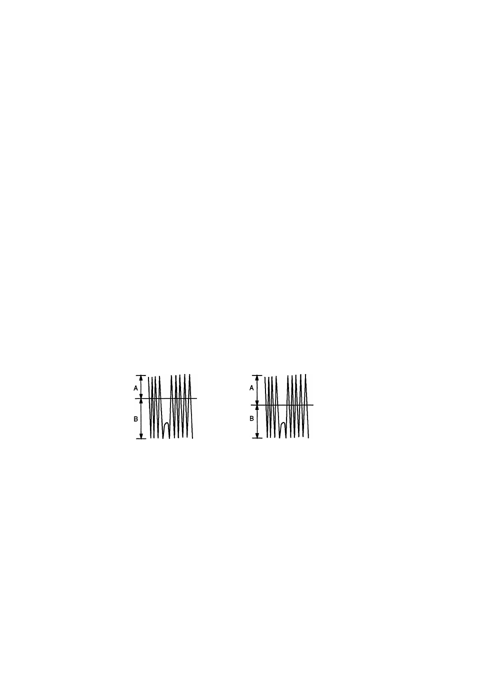
(4) Adjust VR112 (TE. OFS) so that the positive amplitude and negative amplitude of the tracking error signal at CN104
(TP1), Pin 3 (TE) are the same (in other words, so that there Is no DC component).
Note : Perform the run-on adjustment in the section 7 and 8.
■GND
A = B
GND
When there is a DC
component
When there is no DC
component
62