C&D Technologies RS-1476 Standby Battery Vented Cell User Manual
Page 7
2.2 Storing charged and dry batteries
Storage of dry-charged batteries should be in a ventilated, weatherproof, cool and dry building. Remove any
packing container that indicates shipping damage and inspect the thermoplastic jar for cracks or damage. To
prevent foreign material or moisture from entering the cells,
do not remove the plastic film vent seal until cells
are to be filled with electrolyte, charged and prepared for installation.
CAUTION
Upon installation and filling, special attention must be directed to PART 3, Section 1, instructions for
activating and charging dry-charged batteries. Also refer to C&D Form RS-758.
SECTION 3 - PRE-INSTALLATION PLANNING
The cell arrangement, rack(s) and connections are typically installed using generic information provided by C&D.
However, a customized and detailed installation drawing may be obtained from C&D when placing your original
order at an additional charge.
The installer should plan the battery arrangement starting with the positive terminal of the battery to the negative
terminal. Planning should be completed before receipt of the battery. First, sketch a footprint of the rack location.
Check the applicable codes for clearance requirements. Allow sufficient aisle width to permit loading cells directly
to their ultimate location on the rack and clearance for maintenance including overhead clearance. Determine the
battery terminations and locations on the rack layout. The floor loading capacity of the room should be checked,
as well as its capability to hold anchor bolts.
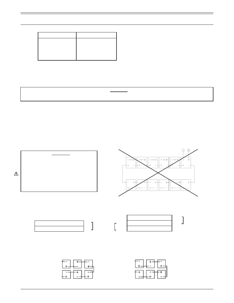
Cells at the end of each row in stepped or tiered racks must be arranged for the shortest cable run between
steps and tiers. See the following illustration. Failure to do so will result in some cables being too short due to
terminal (post) locations especially on multi-cell units.
PART 1
RECEIVING AND INSTALLATION (CONTINUED)
Specific Gravity of Cell
Individual Cell Voltage
1.170
1.215
1.225
1.250
1.275
1.300
2.025
2.063
2.075
2.098
2.123
2.145
+
–
+
Inter-tier
connection
cables
–
+
–
Top tier, x number of cells
Mid tier, x number of cells
Bottom tier, x number of cells
Inter-tier
connection
cables
+
–
–
+
Top tier/step, x number of cells
Bottom tier/step, x number of cells
Top row
Bottom row
Inter-step
cable connection
STEP RACK
Inter-tier
cable connection
TIER RACK
Top row
Bottom row
RS1476/0215/CD
5
www.cdtechno.com
*Fully Charged with Electrolyte
Between High & Low Level Lines
Cell on Open Circuit for 24-72 Hours
If there are an even number of tiers or steps, the battery will terminate on a common end. If there are an odd
number of tiers or steps, the battery will terminate at opposite ends. Polarities below are shown for reference only.
WARNING
The positive and negative terminal
connections of a battery should never
be terminated within a multi-cell unit.
The positive and negative terminal
connections of a battery must be
from different cell containers properly
spaced to provide isolation between
the highest potential differences of
the battery.
TOP ROW
BOTTOM ROW
Unacceptable termination
*Table 2 - Open Circuit Cell Voltages