C&D Technologies RS-1476 Standby Battery Vented Cell User Manual
Page 11
WARNING
Do not use wire pulling compounds, oils, grease or any other material not
specifically authorized by C&D in writing, as these may contain additives
that could damage the plastic containers. Use of any unauthorized solvents
voids warranty.
For seismic (EP) racks, spacers between cells are required.
Add front and end restraining rails and install front-to-back restraining rail tie rods if
supplied, for EP racks. End rails should be placed within one-eighth-inch from end
cells. Reference “Rack Instructions” for more information. Do not tighten end rails
against cells as it can result in jar damage. Tighten tie rods/cell restraining rails to
allow a business card to fit between the cell jar and the restraining rail.
CAUTION
Never move or adjust a rack with batteries loaded on it.
After cells have been installed and connected, remove the orange shipping
vents and install the flame arrestors and dust cover vent assemblies provided in the
accessory kit.
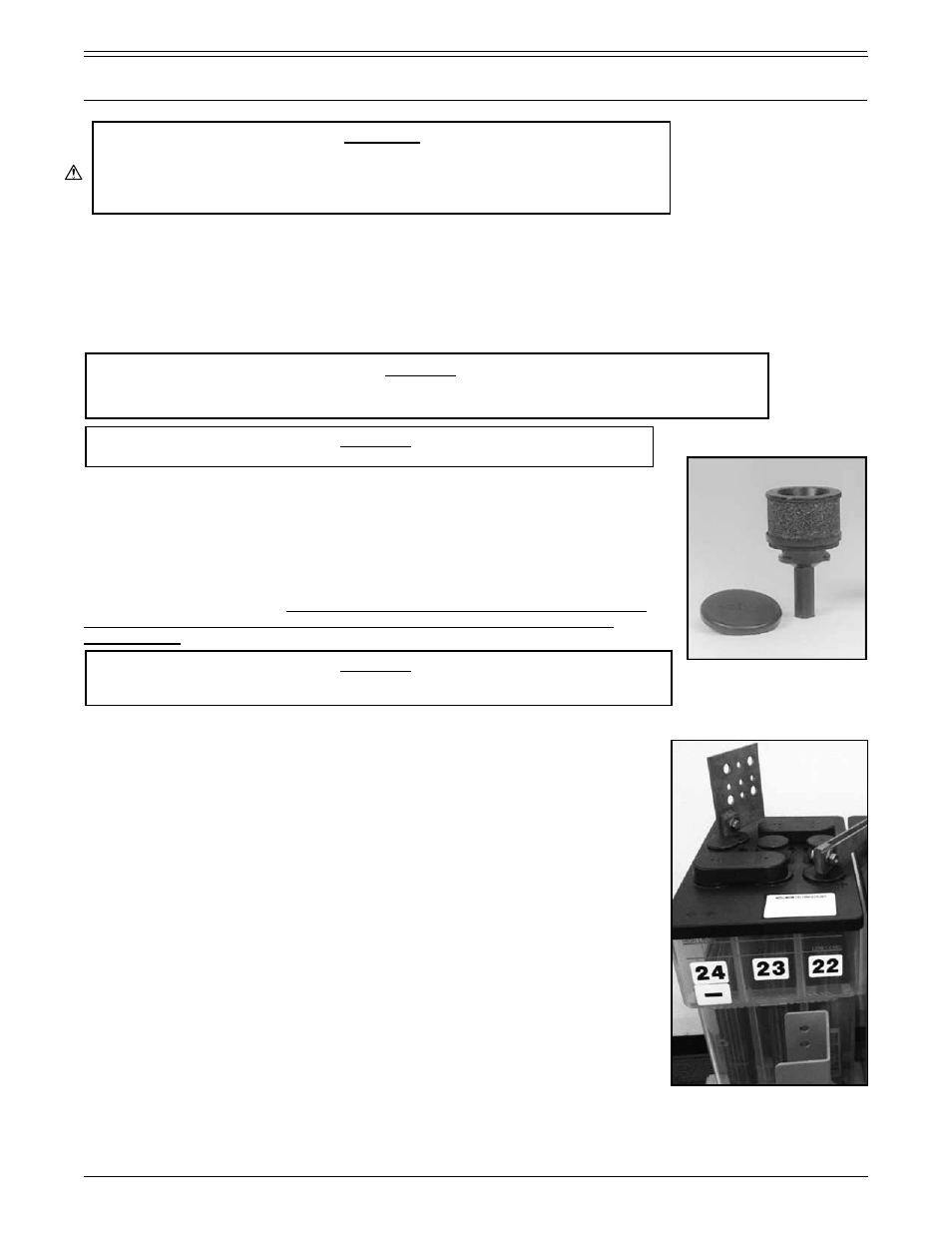
4.4 Flame arrestors
All C&D standby cells use flame arrestors, see Figure 1.4.4. Most cells are shipped
with orange colored vent plugs which must be removed and discarded before
installing the flame arrestors. DRY-CHARGED CELLS MUST BE STORED WITH
ORANGE VENT CAPS AND PLASTIC FILM IN PLACE UNTIL READY FOR
ACTIVATION.
CAUTION
Be sure flame arrestors are installed before making final battery termination
connections. Use caution not to over-tighten.
4.5 Numbering cells, labels and warnings for battery
C&D TECHNOLOGIES, INC. provides labels and warnings to help you maintain
your battery and to apprise you of certain hazards.
Be certain to attach
maintenance and operating labels to cells so they may be read by anyone
working on or in the vicinity of the battery. Reference Part 4, para 1.9 for
examples.
Every cell has an identification label on the cover. This label is very important
since it lists cell type, date code, and order number. This information is needed for
warranty purposes.
The cell ID label is usually placed prior to shipment at the factory. However, some
cells are prepacked in order to enhance delivery. In this case, the ID labels will be
shipped separately and must be placed by the installer during installation.
For ease of identification, all cells of a battery should be numbered. Plastic peel-
and-stick numbers are furnished in the accessories package. Common practice is
to start with “1” at the positive terminal of the battery and follow the electrical circuit
with succeeding numbers. Remove the plastic backing and firmly press the number
into position on the appropriate cell. Be careful not to scratch the plastic jar.
FIGURE 1.4.4 - Flame arrestor vent
with dust cover
Example of an ID label.
Note: Depending on the EP
rack type, spacers
provided may be foam
or molded PVC.
PART 1
RECEIVING AND INSTALLATION (CONTINUED)
RS1476/0215/CD
9
www.cdtechno.com
Note: This is a good time to confirm proper cell orientation, insuring correct polarity
and terminal location (i.e. positive to negative to positive, etc.).
4.6 Preparing electrical contacting surfaces
All electrical contacting surfaces must have a clean, electrolyte-free finish. Any tarnish or discoloration should be
removed with the plater’s brass bristle brush,optional fiber bristle brush, burlap cloth, or medium grade Scotch Brite™.
CAUTION
Where multiple standard type racks are installed end-to-end, no more than one-eighth-
inch of cell length should rest over a support rail that is not rigidly spliced.