C&D Technologies RS-1476 Standby Battery Vented Cell User Manual
Page 15
CAUTION
ELECTRICAL HAzARD — AUTHORIzED PERSONNEL
Before connecting battery to charger, it is important to note that several hazards are associated with
battery systems, particularly those used for large UPS applications where terminal voltages can approach
several hundred volts and currents may exceed several thousand amperes. By exercising proper care and
allowing only properly trained personnel to work on them, batteries should serve you well and perform
without incident. Observe precautions and become familiar with local, state, federal, and professional
codes and procedures. It is advisable to determine if the UPS topology includes an isolation input
transformer. If it does not, an electrical ground reference will be present at the battery.
CAUTION
If proper polarity is not observed when charging the battery, the battery or groups of reverse-connected
cells will be irreparably damaged.
4.10 Connecting battery to charger
Use only direct current (dc) for charging. With the charging source de-energized, connect the positive terminal of
the battery to the positive terminal of the charger or system bus, and the negative terminal of the battery to the
negative terminal of the charger or system bus. Check polarities with a voltmeter to be sure that connections are
correct. Energize the system by following the manufacturer’s procedures.
PART 1
RECEIVING AND INSTALLATION (CONTINUED)
Note: Always complete a record of open circuit voltage, initial charge, float charge readings and connection
resistances with DLRO. Retain the readings in your files for future reference. Any future warranty discussions
will require this information. For convenience, use Form RS-105. A sample is included in this manual. Make
a photocopy of the sample so the original will be available for subsequent use. The service life of your
battery will depend on boost charges (if in storage), its operating temperature, frequency of use and depth of
discharge, discharge rate, and float charge voltage and regulation.
Address the report to:
C&D TECHNOLOGIES, INC.
Attn.: Technical Service Department
1400 Union Meeting Road
Blue Bell, PA 19422
Terminal plates facilitate the connection of multiple power leads. They
are made of heavy copper, tin or lead-plated and formed to permit
connection to posts of various configurations. See Appendix A for
details of the terminal plates supplied in the standard accessory kits.
RS1476/0215/CD
13
www.cdtechno.com
NOTE: C&D recommends the use of lead-plated cable lugs on vented flooded lead acid batteries if
connections will be made directly to the posts of cells
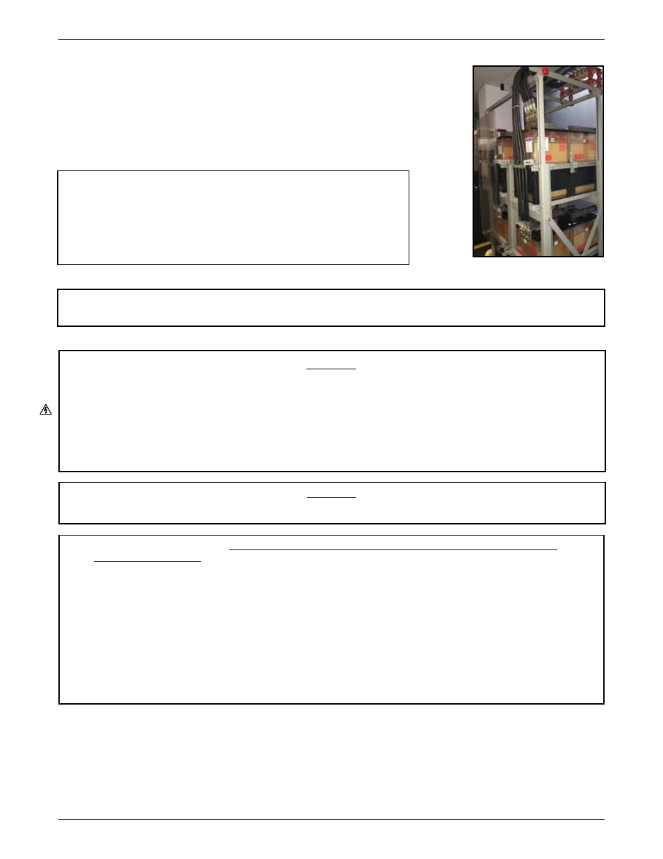
Figure 1.4.9
Caution
Unsupported cables may cause excessive stress to
terminal plates and posts. The maximum unsupported
length of an inter-tier, inter-row or inter-rack cable should
be 3 feet. Cabling dropping from overhead cable supports
may have a maximum unsupported length of 4 feet.