C&D Technologies RS-1476 Standby Battery Vented Cell User Manual
Page 14
When two inter-cell connectors are supplied for connecting cells they must be
placed on opposite sides of the posts. Make the inter-cell connection (positive to
negative) using the bolt assemblies supplied. Refer to Figure 1.4.5.
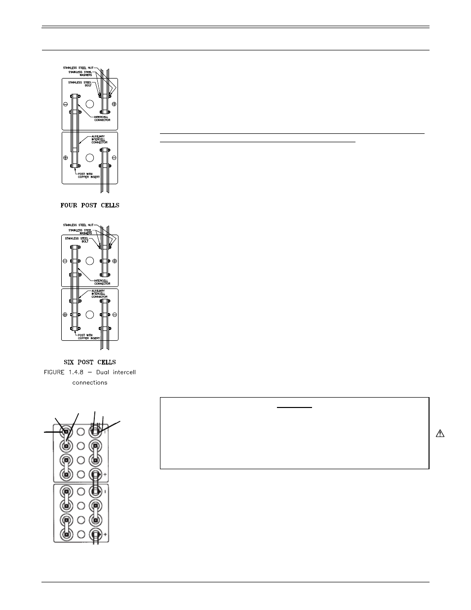
High current batteries may use shorter piggy back inter-cell connectors
applied over the top of the full length inter-cell connectors connecting all
posts. See illustrations for four and six post cells, Figure 1.4.8.
Tighten the connections to the torque values specified in Table 3, using a torque
and box wrench in counter-torque to avoid damaging posts.
4.8 Checking connection integrity
After connecting and torquing all cells in the battery and prior to connecting to
the charger or dc system, recheck the torque of all connections, in sequence,
and immediately check the total voltage of the battery, using a digital dc
voltmeter. Total battery voltage should equal the open circuit voltage (Table
2) of an individual cell multiplied by the number of cells in series connection.
The cell nameplate provides information on the specific gravity of your cell(s).
Refer to Part 4, Section 1.9, for description of nameplate information.
If the battery voltage is less than this value, either your voltmeter is incorrect
or one or more of the cells is installed in reverse polarity. Check and correct
cell polarities. Making this correction will avoid the possibility of charging cells
in reverse and destroying them.
Initial cleaning, surface preparation and torquing establishes the lowest
possible resistance between posts, connectors and lugs – all of which may
have somewhat irregular surface finishes. Subsequent retightening at slightly
lower maintenance torque value (reference table 3) periodically restores initial
connection integrity between clean surfaces.
Over-torquing will distort lead
posts, permanently damaging the cells.
Maintain clean, tight connections. Per Part 4 of this manual, check connection
resistance. Connection maintenance is the responsibility of the battery end
user. Refer to Part 4 for additional maintenance information.
The preferred method of checking connection integrity is by using a digital low
resistance micro-ohm meter (DLRO) and recording the resistance values of
each connection. For new installations remake any connection that is more
than 10 percent above the average value or 5 micro-ohms, whichever is
greater. Refer to the Reference section (Part 4) of this manual for additional
information and IEEE-450 and 484 professional standards.
CAUTION
It is the sole responsibility of the battery end user to check connections.
All connections should be checked at regular intervals, to ensure the
connections are clean and tight. Never operate a battery with loose or
corroded connections. When restoring connections, disconnect the
battery from the load and the charging equipment and follow all the
precautionary measures outlined above.
4.9 Terminal plates, cables and lugs
C&D TECHNOLOGIES, INC. offers a variety of cables, terminal lugs and
special terminal plates as optional equipment for specific battery installations.
Before beginning installation, check the accessories cartons to determine if
the parts ordered have been received. Also check for additional instructions
which may be specific to your application. This should be done before you
schedule installation to permit delivery of any necessary additional hardware.
Standard length inter-row and inter-tier (not inter-aisle or charger) cables are
supplied by C&D. They are flexible, battery cables with lugs, properly sized for
minimal voltage drop. Lead plated lugs are supplied when lugs are attached to
the battery posts.
TWO POST
MULTICELL
STAINLESS STEEL BOLT
STAINLESS
STEEL WASHER
STAINLESS STEEL NUT
INTER-CELL
CONNECTOR
STAINLESS STEEL BOLT
AND WASHER
POST WITH
COPPER
INSERT
PART 1
RECEIVING AND INSTALLATION (CONTINUED)
RS1476/0215/CD
12
www.cdtechno.com