C&D Technologies RS-1476 Standby Battery Vented Cell User Manual
Page 26
1.6 Connection voltage drop
The importance of the integrity of inter-cell, inter-aisle and inter-row connections
has been stated. Loose, dirty, or oxidized connections have higher than normal
resistance and increased voltage drop resulting in less reserve time.
Typically, the designed voltage drop between cells should be 30 millivolts or less.
Voltage drop between rows for standard (inter-tier/inter-step) cables is typically
less than 100 millivolts.
1.7 Measuring connection resistance
Reference Information
IEEE-450 provides a comprehensive description of how to measure connection resistance. Details may be
found in the Annex F of IEEE-450.
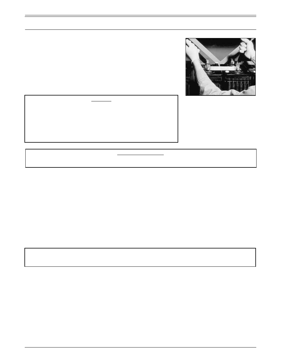
A preferred method of measuring connection resistance uses a sensitive digital micro-ohm meter. See Figure 4.1.7.
To measure connection resistance with a digital, low-resistance ohmmeter, proceed as follows:
• Be sure all connections are clean and torqued to the values specified in Table 3, Section 1.4.7 for re-torque.
• With the battery on float charge or open circuit, take measurements post to post. (Positive post of one cell to the
negative post of the next cell.)
• Starting at one end of the string, work toward the other end, recording micro-ohm resistance’s and noting
connections with unacceptable resistance’s or resistance values that exceed the average by 20 percent.
NEVER
USE THE DLRO TO TAKE A READING ACROSS A CELL OR THE TERMINALS OF THE BATTERY. THIS
COULD SERIOUSLY DAMAGE THE INSTRUMENT.
• Recheck connections that exhibit unacceptable resistance.
Clean and re-torque to the original (initial) torque
value, when required.
Note: Whenever a connection must be disassembled and reworked be certain to re-torque the connection
to the original (initial) installation torque value.
Compare resistance readings with the original installation readings and records taken when the battery was first
installed. Connections that still exhibit unacceptable resistance after cleaning and re-torquing may indicate the presence
of improperly sized or damaged cables or inter-cell connectors. Contact your C&D representative for assistance.
1.8 Electrolyte containment
Although it is unlikely that a properly maintained battery will exhibit a container failure and electrolyte leakage,
electrolyte containment systems are required by the Uniform Fire Code — Article 64. These systems are available from
C&D. Consult your C&D representative or C&D directly for assistance in specifying and ordering one of these systems.
FIGURE 4.1.7 Measuring connection
resistance with DLRO
PART 4
REFERENCE INFORMATION, TROUBLE SHOOTING & EXTENDED MAINTENANCE (CONTINUED)
RS1476/0215/CD
24
www.cdtechno.com
CAUTION
Checking voltage drop with conventional voltmeters requires that
measurements be taken while the battery is discharging at its rated
discharge current. The resistance may be calculated using Ohm’s
law. Note that cycling will shorten the life of the battery, (refer to
“Float versus Cycle Life” in Section 4). For this reason, the use
of digital, low-resistance ohmmeters is recommended. This type
of equipment allows the measurement of connection resistance
without discharging or cycling the battery.