C&D Technologies RS-1476 Standby Battery Vented Cell User Manual
Page 17
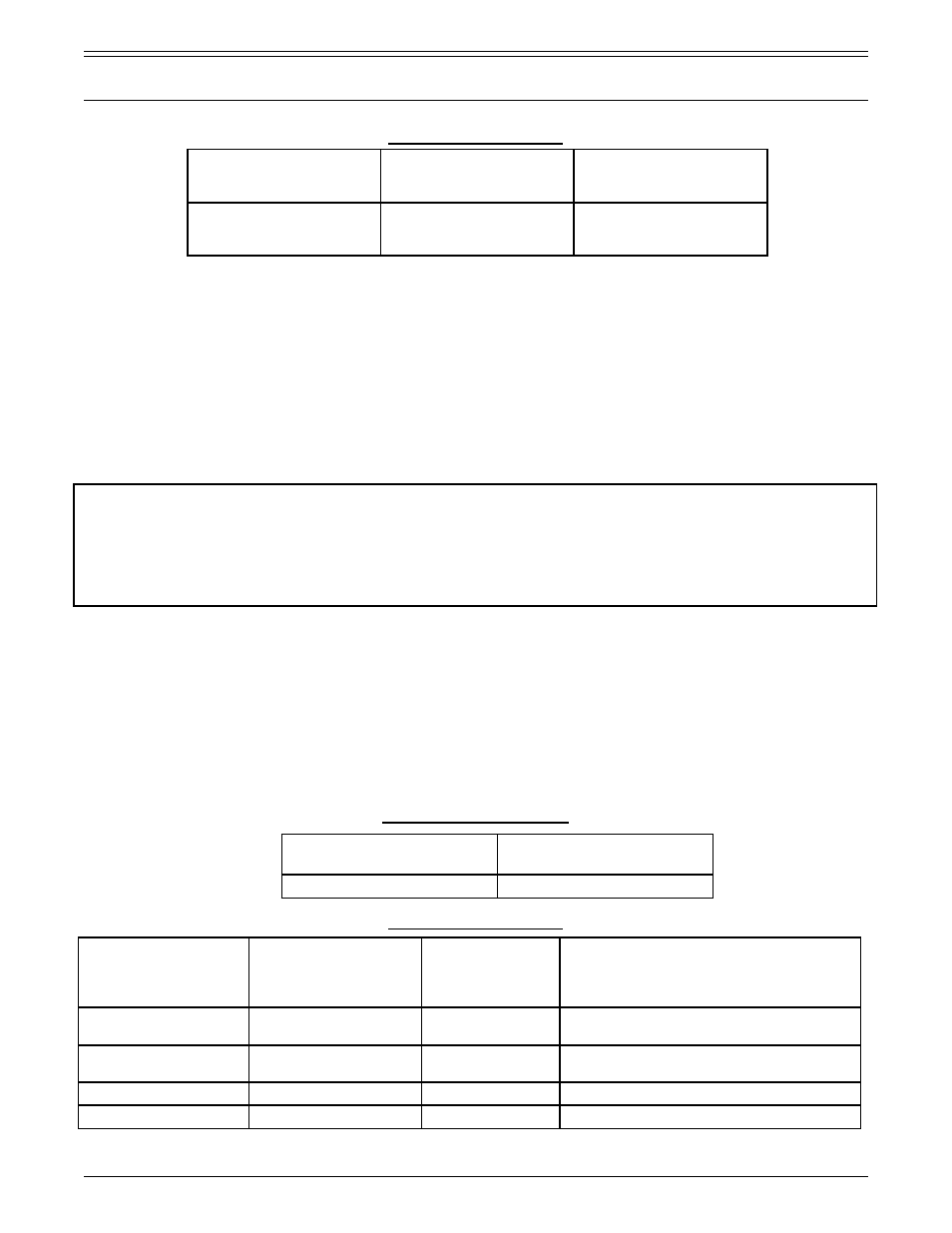
LEAD CALCIUM CELLS
Note: Applies to average cell voltage. Battery system voltage should be set at average cell voltage multiplied by the
number of cells in battery
CHARGE COMPLETION: The charge is complete when the lowest cell voltage is stable over three consecutive
hourly readings, the voltage of the lowest cell is within 0.05 V of the string average, and the specific gravity of the
cells are within +0.010/- .005 of the average of the string (see Part 4 section 1.3). The string charge current (amps)
should remain the same over a 3 hour period by the end of the initial charging period.
Note on the specific gravity of the cells - The electrolyte of the cells is set at the factory to the nominal specific
gravity +0.010/-0.005, at 77°F (25°C), with the electrolyte level between the high and low level lines as specified in
Part 4, section 1.3 of this manual.
Note: As the cell operates and the electrolyte is depleted and replenished, and the state of charge changes due
to usage of the battery leading to sulfation and/or stratification, the specific gravity of the electrolyte is impacted
accordingly and specific gravity measurements may not reflect the actual cell gravity. In such cases the use of the
string average specific gravity measurements is recommended in troubleshooting possible outlying cells versus their
shift from nominal. For a new cell following proper equalization methods the measured specific gravity should reflect
the factory requirements for nominal gravity on the initial float charge. Please reference to Part 4, Section 1.3.
1.2 Float charge
Standby batteries are continuously connected to control circuits which must be energized at all times. Connected
to a load in parallel with a continuously operating charger, these batteries assure instantaneous support of the
load in the event of a power failure or brownout. In addition to operating the connected load, the power supply
maintains the standby battery in a fully charged condition. This parallel interconnection and operation is called
float service.
For optimum service, adjust the charger to the float voltages shown in Table 5.
Table 5 - Float Voltage Per Cell (VPC)
LEAD-ANTIMONY CELLS
LEAD-CALCIUM CELLS
PART 2
CHARGING AND OPERATION OF BATTERY (CONTINUED)
Nominal Specific
Gravity
See Part 4, Sec. 1.3)
Maximum Average
Volts Per Cell VPC
(see note)
Time in Hours
at maximum
cell voltage
1.215
1.250
1.300
2.38
2.43
2.50
24 - 100
24 - 100
24 - 100
Nominal Specific Gravity
(See Part 4, Sec. 1.3)
Float Voltage Setpoint Range
77ºF (25ºC)
1.215
2.15 – 2.18
Nominal Specific
Gravity
(See Part 4, Sec. 1.3)
Float Voltage
Setpoint Range
77ºF (25ºC) (1)
Allowable
Individual Cell
Voltage Range
77ºF (25ºC) (2)
Applications
1.215
2.17 – 2.22
2.12 - 2.27
Telecom except LCT-HP,
MCTII and MCT-HP
1.215
2.20 – 2.25
2.12 - 2.29
UPS, Switchgear & Control (Utility),
LCT-HP / MCT II / MCT-HP
1.250
2.22 – 2.27
2.15 - 2.32
All
1.300
2.32 – 2.36
2.23 - 2.41
All
RS1476/0215/CD
15
www.cdtechno.com