5300_install_2_3.pdf, Installation, Quick reference – Braeburn 5300 3H-2C Installer Manual User Manual
Page 2
2
3
Replacing Existing Thermostat (continued)
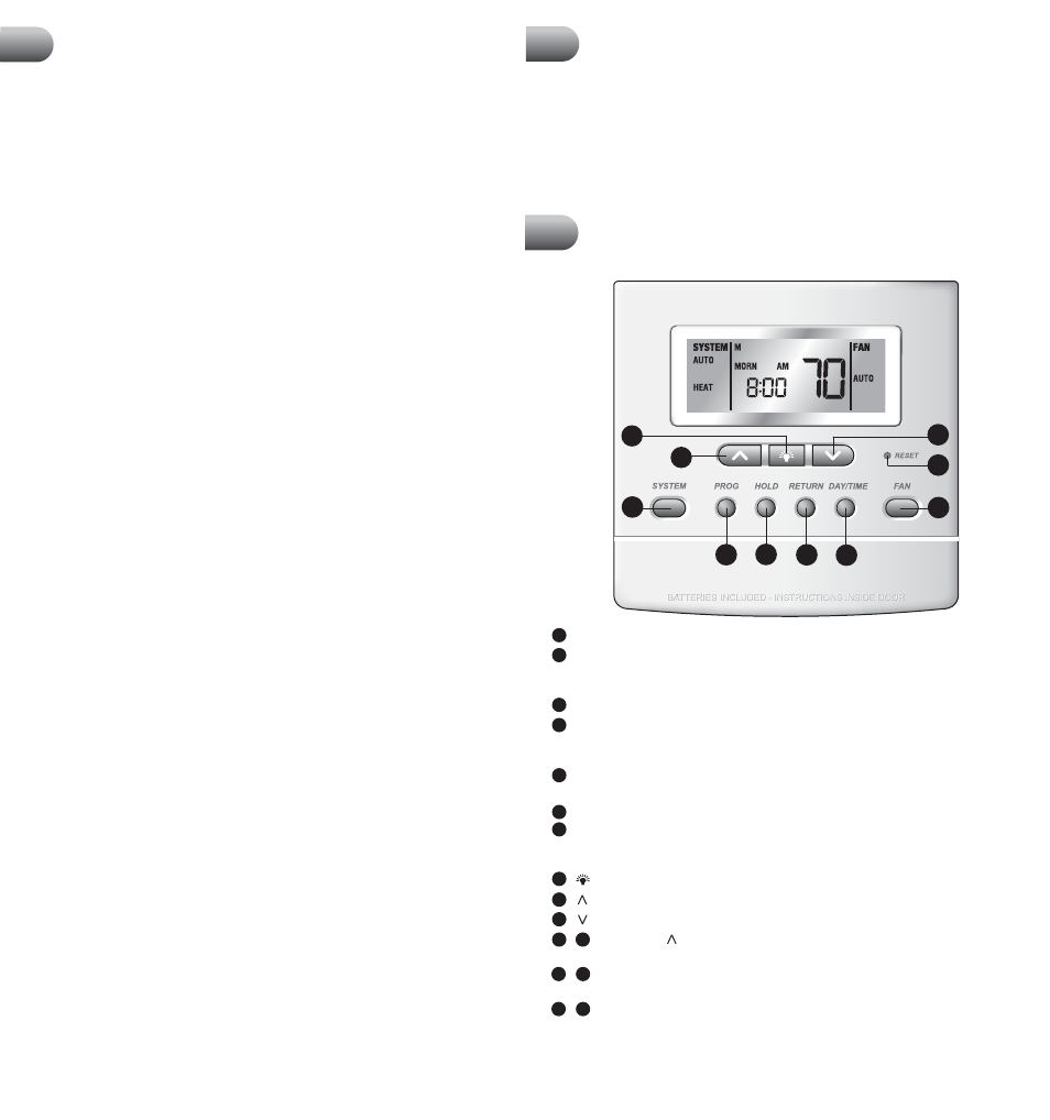
SYSTEM Button: Selects AUTO (Heat/Cool), COOL, OFF, HEAT or EMER.
PROG Button: Press to enter the program setup mode where you can select the time,
temperature and fan setting for each program period. Scrolls backwards between
user/installer setup screens.
HOLD Button: Enables or disables extended hold mode or temporary program override.
RETURN Button: Press and hold for 4 seconds to enter the user settings mode (see user
manual). Scrolls between user/installer setup screens. Returns unit to normal mode when
in program mode.
DAY/TIME Button: Enters time and day setting mode. Selects individual days in
program mode.
FAN Button: Selects AUTO, ON, CIRC (recirculate) and PROG (program) modes.
RESET Button: Resets time, program and some user settings back to the factory default.
See section 4 for a list of functions that will return to their factory default settings after
the RESET button is pressed.
Button: Turns on backlight for 10 seconds.
Button: Increases setting (time, temperature, etc.). Scrolls between option settings.
Button: Decreases setting (time, temperature, etc.). Scrolls between option settings.
RETURN and Buttons: Press both buttons at the same time and hold for 4
seconds to enter the installer settings mode (see section 4).
RETURN and PROG Buttons: Press both buttons at the same time to exit the installer
settings mode.
PROG and HOLD Buttons: Press and hold both buttons at the same time to view the
outdoor temperature if an outdoor sensor is connected.
CLEAR Button: Located on the back of the thermostat. Resets the thermostat to all
factory default settings. See section 4 for a complete list of settings.
1
2
3
4
5
6
7
8
9
10
4
9
+
Model 5300 shown with cover open
NOTE: This thermostat is designed for use on low voltage 24 volt AC single stage
or multi-stage systems, including heat pumps with up to three stages of heating
and two stages of cooling. Do not use this thermostat on systems with voltage
higher than 30 Volts AC. This thermostat requires a transformer common wire for
proper installation if used as a hardwired thermostat.
Installation
2
cont.
Installing New Thermostat
Quick Reference
3
2
4
+
4. After labeling the old wires, loosen each connection and remove them from
old sub-base. Secure the wires to prevent them from slipping into the opening
in the wall.
5. Remove the old sub-base from the wall, again being careful that the wires do
not slip into the opening in the wall.
6. Use the chart on page 1 to determine the new thermostat connections. As an
example, if the old thermostat had a G or F connection, it goes to G on the new
thermostat. It may be helpful to use the chart by circling (with a pencil or pen)
the letter of each wire removed from the old thermostat.
NOTE: When installing this thermostat in a new location, following a few simple
guidelines and the applicable building codes will give the best results. Install the
thermostat in a location that provides good airflow by avoiding areas behind
doors, near corners, air vents, direct sunlight or heat generating devices. The
wiring must conform to all building codes and ordinances as required by local
and national code authorities having jurisdiction for this installation.
1. Always turn off the power to the air conditioning and heating system prior
to installing this thermostat.
2. Locate the release latch on the bottom (not the back) of the thermostat.
Press the release latch in and separate the body from the sub-base of the
thermostat. Because this thermostat has 14 possible connection points, you
may need to apply moderate force to separate the parts.
3. Set the thermostat electronics and cover down on a clean surface. Place the
sub-base on the wall in the desired location.
4. Using the slotted mounting holes in the sub-base, mark the placement of the
mounting holes through the slots and onto the wall. Ensure the wires come out
of the wall into the center hole of the sub-base.
5. After verifying the drill will not damage items in the wall, use a 3/16 drill to
create the mounting holes. Gently tap the supplied plastic anchors into the
holes in the wall.
6. Place the thermostat sub-base against the wall in the desired location. Ensure
the thermostat is level, the wires are inserted in the opening, and the mounting
holes are aligned with the slots on the sub-base.
7. Fasten sub-base to wall using supplied screws into the plastic wall anchors.
8. Connect wires to the quick wiring terminal blocks. Use the wiring diagram
chart to ensure the old and new connections are correct.
9. To prevent electrical shorts and potential damage to the thermostat, make
sure all wire connections are secure and not touching each other.
10.Locate the thermostat body, and ensure the cover is still installed properly.
Using the mounting tabs on the top of the sub-base as a guide or hinge, close
up the thermostat case by pivoting the body and cover closed. The latch on the
bottom of the thermostat will click when the case is properly closed. Because
this thermostat has 14 possible connection points, you may need to apply
moderate force to close the case.
Installation
2
cont.
Installing New Thermostat
(continued)
11. Flip the front thermostat cover up and open the battery compartment door.
12. Locate the positive [+] ends of the batteries and match them with the positive
[+] terminals located in the battery compartment. Install the two new “AA”
alkaline batteries (supplied). Close battery compartment door.
13. Restore system power and proceed to programming and system checkout.
3
2
+
8
9
7
1
6
2
3
4
5
10