AERCO ECS Retrofit User Manual
Page 52
52
6. Connect the Line, Neutral and Ground leads to the TB-2 terminals shown in Figure 4-18.
7. Close the swing-down panel after the power leads are secured to TB-2. Tighten the captive
screw to secure the recessed panel.
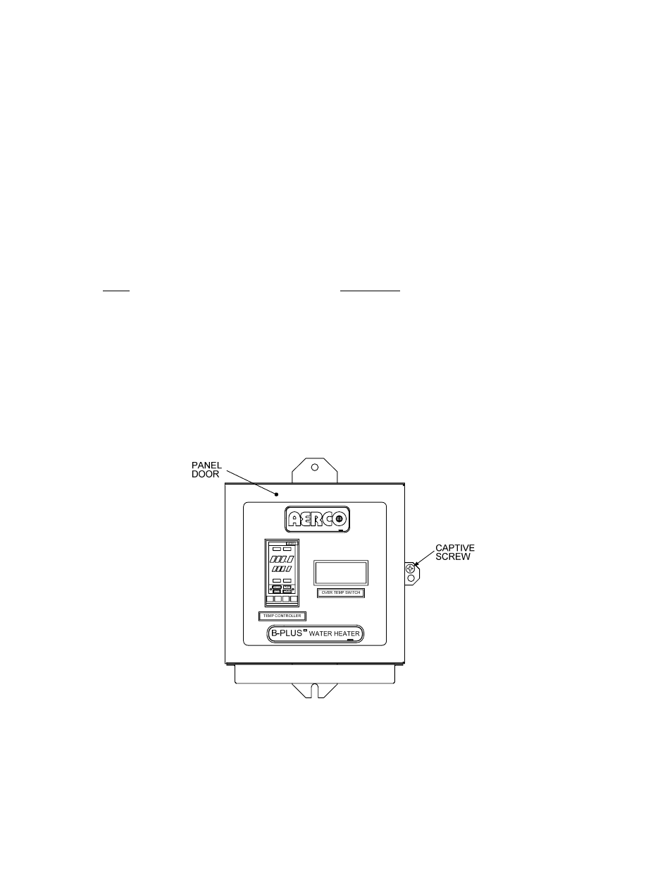
8. Close the front door of the ECS Control Box and tighten the captive screw to secure it in the
closed position.
9. Check the labels on the Control Box cables and connect them to the following components:
NOTE
The BOILER WATER IN and BOILER WATER OUT cables shown with an
asterisk (*) are used on Water-to-Water Heaters ONLY (E-Plus or Double-Wall
Models).
Label
Connect To:
VALVE ACTUATOR
3-Pin Molex Connector on Actuator
FLOWMETER
5-Pin
Connector
on
Flow
Meter
OUTLET TEMP
4-Pin Connector on Dual Sensor (Outlet Port)
*BOILER WATER IN
2-Pin Connector at Heating Fluid Inlet
*BOILER WATER OUT
2 Pin Connector at Heating Fluid Outlet
Figure 4-16. ECS Control Panel Front View
- AERClean (12 pages)
- ProtoNode Gateway Rev 1 (with internal LEDs) (64 pages)
- ProtoNode Gateway Rev 3 (with external LEDs) (126 pages)
- Control System (ACS) (144 pages)
- Belimo F6...HD/HDU Series Valve (44 pages)
- Belimo AF120-S US Actuator (9 pages)
- Belimo AMX24-MFT Actuator (9 pages)
- Belimo GKX24-MFT Actuator (9 pages)
- Belimo Motorized Valves Installation (20 pages)
- BMS II BOILER (108 pages)
- BMS II BOILER MODBUS Communication (100 pages)
- BMS 168 (86 pages)
- Boiler Valve Controller (BVC) PRIOR to Serial-12-840-1 (35 pages)
- Boiler Valve Controller (BVC) (38 pages)
- Buffer Tanks (14 pages)
- Combination Control Panel (CCP) (4 pages)
- XPC GATEWAY Communications (193 pages)
- Domestic Water Storage Tank (19 pages)
- Steam Traps (6 pages)
- X100 – Inhibitor (4 pages)
- AM Series Boiler User Manual (156 pages)
- AM Series Boiler Cascade Sequencer Controller (26 pages)
- AM Series Boiler Modbus Interface Manual (18 pages)
- BMK 1.5 LN October 2012 (166 pages)
- BMK 1.5 LN July 2011 (152 pages)
- BMK 1.5 LN June 2010 (123 pages)
- BMK 1.5 LN May 2009 (111 pages)
- BMK 1.5 LN Dual Fuel Feb 2013 (162 pages)
- BMK 1.5 LN Dual Fuel June 2010 (139 pages)
- BMK 1.5 LN Dual Fuel Jan 2009 (126 pages)
- BMK 1500-2000 (188 pages)
- BMK 1500DF (196 pages)
- C-More Control Panel (162 pages)
- BMK 2.0 LN October 2012 (172 pages)
- BMK 2.0 LN Natural Gas (SN G-11-1861 and above) (170 pages)
- BMK 2.0 LN Nat. Gas June 2010 (125 pages)
- BMK 2.0 LN Natural Gas 2008 (111 pages)
- BMK 2.0 LN Nat. Gas for Mass. only (113 pages)
- BMK 2.0 LN Dual Fuel Serial G-11-2402 and UP (160 pages)
- BMK 2.0 LN Dual Fuel Nov 2010 (139 pages)
- BMK 2.0 LN Nat. Gas (112 pages)
- BMK 2.0 LN for Mass. only (114 pages)
- BMK 3.0 LN Dual-Fuel Series Gas Fired Low NOx Boiler System (136 pages)
- BMK 3.0 LN Natural Gas July 2011 (129 pages)
- BMK 3.0 LN Nat. Gas Jan 2011 (129 pages)