AERCO ECS Retrofit User Manual
Page 41
41
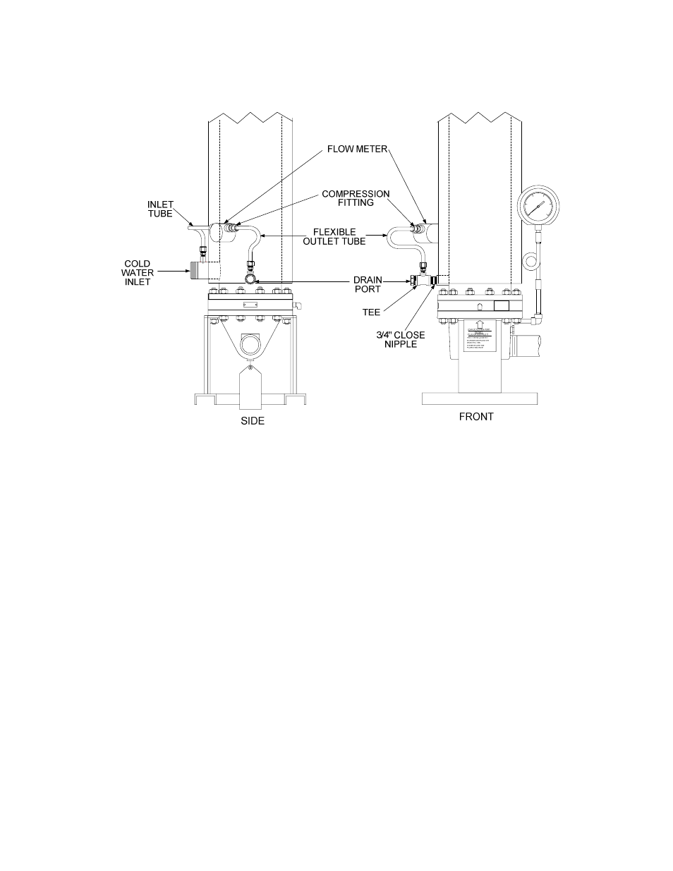
Figure 4-7. Double-Wall Heater Flow Meter Location
4.3.1 Flow Meter Installation For Helitherm Heaters
For A-Plus, B-Plus, B-Plus II and E-Plus Heaters, the Flow Meter connections are made at the Bottom
Head of the Heater. The Flow Meter Inlet side connects to the Cold Water Inlet using Rigid Tubing.
However, the Outlet side of the Flow Meter connects to the Drain Outlet using Flexible Tubing. A
typical B-Plus or B-Plus II installation is shown in Figures 4-5 and 4-6. Refer to these Figures when
performing the following steps:
1. Obtain the Flow Meter, Rigid Inlet Tube, Flexible Outlet Tube and Compression Fittings from
the Retrofit Kit. Refer to Appendix A for the applicable part numbers for the tubing and fittings
required for the unit being retrofitted.
2. Attach the Rigid Inlet Tube and Flexible Outlet Tube to the Flow Meter using the fittings
provided in the kit.
3. Next, obtain the Modified 2” NPT Nipple (9006) from the Retrofit Kit.
4. Remove the existing 2’ NPT Nipple from the Drain Outlet on the Bottom Head.
5. Install the new Modified 2” NPT Nipple in the Bottom Head. Attach the ¼ NPT coupling to the
tapped hole in the Modified Nipple.