AERCO ECS Retrofit User Manual
Page 42
42
6. Connect the Flow Meter Outlet Flexible Hose to the Modified Nipple on the Drain Outlet using
the compression fitting. Connect the Rigid Flow Meter Inlet Tube to the Cold Water Inlet using
the compression fitting provided in the kit.
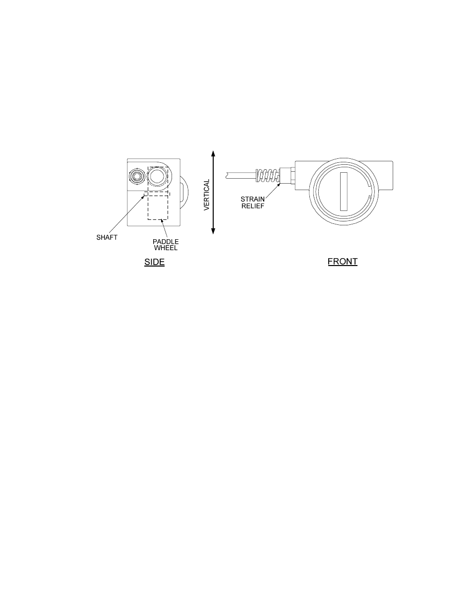
7. Position the Flow Meter so that the Paddle Wheel is in the “Vertical” plane as shown in Figure
4-8. Tighten all Flow Meter connection fittings.
Figure 4-8. Flow Meter Orientation
4.3.2 Flow Meter Installation For Double-Wall Heaters
Flow Meter connections for Double-Wall Heater Models DW-24, DW-45 and DW-68 are made on the
Shell as shown in Figure 4-7. As with Helitherm Models, Rigid Tubing is used for the Flow Meter Inlet
connection to the Cold Water Inlet and Flexible Tubing is used for the Outlet connection at the Drain.
Flow Meter installation is accomplished as follows:
1. Obtain the Flow Meter, Rigid Inlet Tube, Flexible Outlet Tube and Compression Fittings from
the Retrofit Kit.
2. Attach the Rigid Inlet Tube and Flexible Outlet Tube to the Flow Meter using the fittings
provided in the kit.
3. Next, obtain the 3/4” Close Nipple (9-234) and 3/4 x 1/4 x 3/4” Tee (59032) from the Retrofit
Kit.
4. If installed, remove the 3/4” NPT Plug from the Drain Port on the Heater Shell (Ref. Figure 2-2,
sht 1).
5. Install the Close Nipple and Tee in the Drain Port (Figure 4-7)
6. Connect the Flow Meter Outlet Flexible Tubing to the Drain Outlet Tee as shown in Figure 4-7.
Connect the Rigid Inlet Tube from the Flow Meter to the Cold Water Inlet using the
compression fitting provided.
7. Position the Flow Meter so that the Paddle Wheel is in the “Vertical” plane as shown in Figure
4-8.