AERCO ECS Retrofit User Manual
Page 11
11
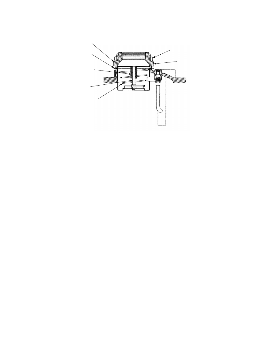
FLANGE
GASKET
SPRING PLATE
ASSEMBLY
SPRING
VALVE PLUG
ASSEMBLY
HEX NUTS (4)
HOT WATER
OUTLET FLANGE
OUTLET
FLANGE
Figure 2-3. Anticipator Check Valve (Load Alert) Assembly
NOTE
For Double-Wall Heater Models (DW-24, DW-45, DW-68), the items removed
in paragraph 2.4 are located on the Shell of the Heater instead of the Bottom
Head. Therefore, refer to Figure 2-2 for Double-Wall Models.
2.4 Removal of Items Connected to Bottom Head
In order to install several new ECS components, the Drain Ball Valve must be disconnected and the
Cold Water Inlet Orifice Disc replaced. The locations of these items are shown in Figure 2-1, sheet 3.
Proceed as follows:
1. Disconnect any external piping connected to the Cold Water Inlet and Drain Ball Valve Outlet
on the Bottom Head.
2. Locate the Orifice Disc in the Cold Water Inlet (Figure 2-1, sheet 3).
3. Using a pair of pliers, disconnect the snap ring securing the Disc in the Bottom Head.
4. Remove the clip and the Orifice Disc from the Bottom Head. This Orifice Disc will be replaced
in Section 4 with a new Disc provided in the Retrofit Kit.
5. Next, temporarily remove the Drain Ball Valve from the Bottom Head (Figure 2-1, sheet 3).
Retain this Ball Valve for reinstallation in Section 4.