7 ecs control box installation – AERCO ECS Retrofit User Manual
Page 51
51
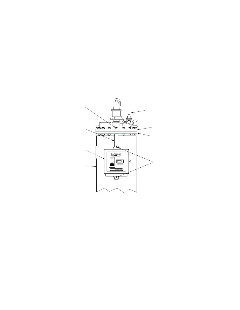
4.7 ECS Control Box Installation
The ECS Control Box is attached to the Water Heater using the old Control Box Mounting Bracket
removed in Section 2. Install the new ECS Control Box in accordance with the following steps:
1. Attach the ECS Control Box to the Mounting Bracket using the two 1/4-20 x 1/2 “ screws and
washers provided in the Retrofit Kit.
2. Insert the top end of the Mounting Bracket under the previously loosened hex nut at the top of
the Heater Shell (Figure 4-15). After the Bracket is vertically aligned, tighten the hex nut to
secure the Mounting Bracket and ECS Control Box to the Water Heater.
TEMP CONTROLLER
B+II
OVER TEMP SWITCH
SHELL
ECS CONTROL
BOX
MOUNTING
BRACKET
MOUNTING
BRACKET
SCREWS
SHELL FLANGE
SOLENOID
VALVE
HEX NUTS
& STUD
TOP HEAD
Figure 4-15. ECS Control Box Mounting Location
NOTE
External power at 120 to 240 VAC, 50/60 Hz is required to operate the
circuitry contained in the ECS Control Box. Power connections are made
internally by routing the power wiring through the cutout provided on the right
side of the Control Box.
3. Next, loosen the captive Phillips head screw on the right front portion of the Control Box
(Figure 4-16) to open the hinged door.
4. Swing open the door and loosen the captive Phillips head screw at the top of the recessed
panel (Figure 4-17). Swing down the panel to access terminal block TB-2 (Figure 4-18)
5. Feed the external 120 to 240 VAC, 60 Hz) power leads through the cutout in the right side of
the ECS Control Box.