Installation, operation & maintenance – AERCO Modulex General Manual User Manual
Page 41
INSTALLATION, OPERATION & MAINTENANCE
6-7
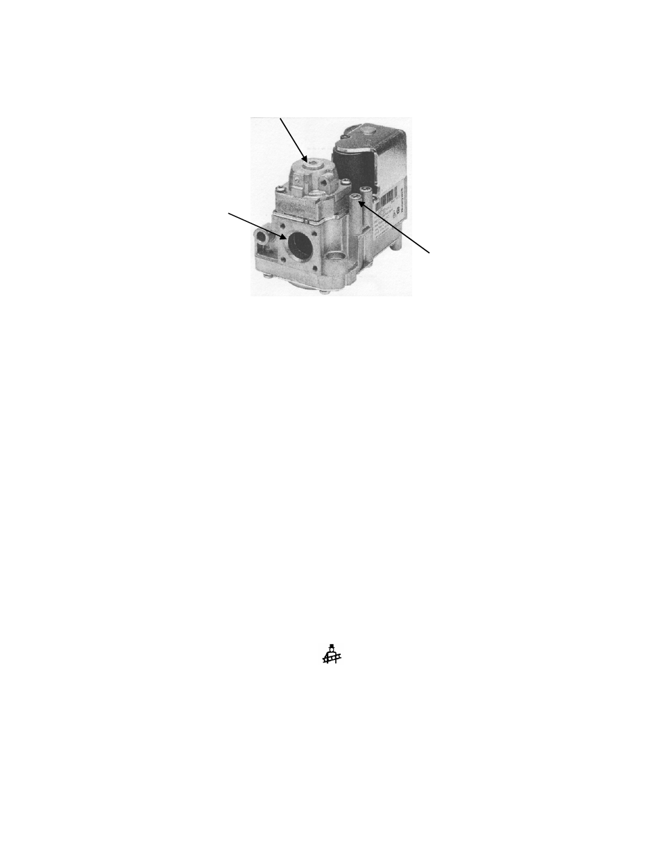
Figure 6-2. Gas Valve Adjustment
1. Refer to Figure 6-2 and locate the outlet pressure tap for the gas valve of the first Boiler Stage.
2. Rotate the outlet pressure tap screw 1/2 turn counterclockwise to open.
3. Attach the plastic tubing between the pressure tap and the manometer.
4. Open the water supply and return valves to the unit and ensure that the system pumps are
running.
5. Ensure that the external gas supply valve to the boiler is open.
6. Set
the
ON/OFF switch on the front of the boiler to the ON position.
NOTE
When performing the remaining steps in the combustion calibration procedure, refer to
Figures 1 and 2 in Modulex E8 Controller Operation & Wiring Guide GF-115-C for
locations and descriptions of the controls and displays on the Controller.
7. With the Controller hinged panel closed, turn the Rotary Knob clockwise and monitor the
displayed symbols on the lower right portion of the display. The symbols will increment from left to
right and show the appropriate symbols for each mode: AUTO MODE 1, AUTO MODE 2,
SUMMER MODE, DAY MODE, NIGHT MODE and finally SERVICE MODE. The SERVICE
MODE symbol will appear at the far right of the display and will look as follows:
8. With the above symbol displayed, open the swing-down hinged panel of the Controller.
INSTALLATION will be displayed.
9. Next, turn the Rotary Knob counterclockwise until SERVICE appears in the display.
10. With SERVICE displayed, press the Program Key on the Controller.
CAP SCREW / OFFSET
ADJUSTMENT
OUTLET
OUTLET PRESSURE TAP
(NORMAL MANIFOLD
PRESSURE)